Download
1 / 48
480 likes | 644 Views
Understand layers of protection & automated safety systems for high reliability & emergency response in industrial processes. Learn about automation strategies, control systems, multiple layers of safety, and equipment protection. Explore control strategies like cascade control & split-range control. Discover how split-range control, override/select control, and redundancy contribute to safe operation. Implement these concepts to ensure a robust safety hierarchy & protection against equipment failures.

E N D
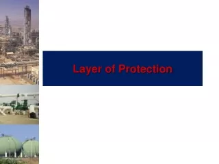
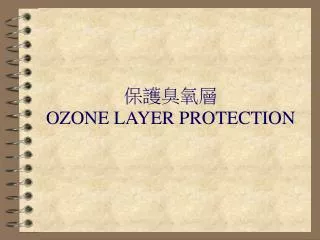
Layers of Protection for High Reliability EMERGENCY RESPONSE CONTAINMENT RELIEF SIS ALARMS BPCS • Strength in Reserve • BPCS- Basic process control • Alarms - draw attention • SIS- Safety interlock system to stop/start equipment • Relief- Prevent excessive pressure • Containment - Prevent materials from reaching, workers, community or environment • Emergency Response - evacuation, fire fighting, health care, etc. A U T O M A T I O N
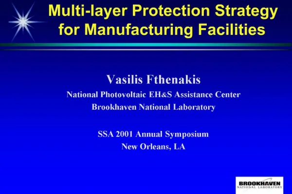
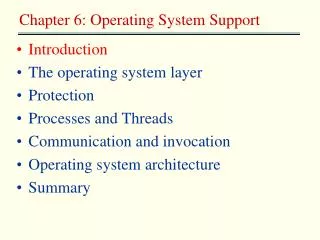
Safety Through Automation • Four Layers in the Safety Hierarchy • Methods and equipment required at all four layers • Process examples for every layer • Workshop
All Processes must have Safety Through Automation Safety must account for failures of equipment (including controller) and personnel Multiple failure must be covered Responses should be limited, try to maintain production if possible Automation systems contribute to safe operation
Redundancy – Key Concept in Process Safety Seriousness of event Four independent protection layers (IPL)
Objective of process Control Control systems are designed to achieve well-defined objectives, grouped into seven categories. 1. Safety 2. Environmental Protection 3. Equipment Protection 4. Smooth Operation & Production Rate 5. Product Quality 6. Profit 7. Monitoring & Diagnosis We are now emphasizing these topics
1. Basic process Control System (BPCS) • Technology - Multiple PIDs, cascade, feedforward, etc. • Always control unstable variables (Examples in flash?) • Always control “quick” safety related variables • - Stable variables that tend to change quickly (Examples?) • Monitor variables that change very slowly • - Corrosion, erosion, build up of materials • Provide safe response to critical instrumentation failures • - But, we use instrumentation in the BPCS?
Control Strategy Feedback Control Single-loop feedback Overcoming disturbances Cascade Feed forward Ratio Constraints Split-range, override/select control Multivariable multi-loop Decoupling Multivariable control
Level Control on a Tank Ordinary Feedback Control Cascade Control With cascade level controller, changes in downstream pressure will be absorbed by the flow controller before they can significantly affect tank level because the flow controller responds faster to this disturbance than the tank level process. Without a cascade level controller, changes in downstream pressure disturb the tank level.
Reactor Temperature Control Cascade Control With cascade, changes in the cooling water temperature will be absorbed by the slave loop before they can significantly affect the reactor temperature.
Multiple Cascade Example This approach works because the flow control loop is much faster than the temperature control loop which is much faster than the composition control loop.
Level Control: Feedback vsfeedforward Feedback Feedforward Feedback-only must absorb the variations in steam usage by feedback action only. Feedforward-only handle variation in steam usage but small errors in metering will eventually empty or fill the tank.
Level Control: Feedforward-Feedback Combined feedforward and feedback has best features of both controllers.
Split Range Control: Another Example Signal to Control Valve (%) Larger Valve Smaller Valve Total Flowrate • Sometimes a single flow control loop cannot provide accurate flow metering over the full range of operation. • Split range flow control uses two flow controllers • One with a small control valve and one with a large control valve • At low flow rates, the large valve is closed and the small valve provides accurate flow control. • At large flow rates, both valve are open.
Application of Split Range Control: pH Control Split range for this valve • Strategy: control of pH using ratio of NaOH to acid waste water • Due to dynamic behaviour, Split range is also required
Titration Curve for a Strong Acid-Strong Base System • Therefore, for accurate pH control for a wide range of flow rates for acid wastewater, a split range flow controller for the NaOH is required.
Override/Select Control • Override/Select control uses LS and HS action to change which controller is applied to the manipulated variable. • Override/Select control uses select action to switch between manipulated variables using the same control objective.
Column Flooding Constraint Control Lower value of flowrate is selected to avoid column flooding
BPCS- measurement redundancy How would we protect against an error in the temperature sensor (reading too low) causing a dangerously high reactor temperature? Highly exothermic reaction. We better be sure that temperature stays within allowed range! Cold feed TC
How would we protect against an error in the temperature sensor (reading too low) causing a dangerously high reactor temperature? Use multiple sensors and select most conservative! Cold feed > Controller output TY Selects the largest of all inputs > TC TY T1 Measured value to PID controller T2
Summary of Control Strategies Feedback Control Enhancement of single-loop Feedback control Cascade, split-range, override control Feedforward and Ratio Control Computed Control (e.g. reboiler duty, internal reflux etc) Advanced Control Inferential control Predictive control Adaptive control Multivariable control
2. Alarms that require actions by a Person • Alarm has an anunciator and visual indication • - No action is automated! • - A plant operator must decide. • Digital computer stores a record of recent alarms • Alarms should catch sensor failures • - But, sensors are used to measure variables for alarm checking?
2. Alarms that require actions by a Person • Common error is to design too many alarms • - Easy to include; simple (perhaps, incorrect) fix to prevent repeat of safety incident • - example: One plant had 17 alarms/h - operator acted on only 8% • Establish and observe clear priority ranking - HIGH = Hazard to people or equip., action required - MEDIUM = Loss of RM, close monitoring required - LOW = investigate when time available
3. Safety Interlock System • Automatic action usually stops part of plant operation to achieve safe conditions • - Can divert flow to containment or disposal • - Can stop potentially hazardous process, e.g., combustion • Capacity of the alternative process must be for “worst case” • SIS prevents “unusual” situations • - We must be able to start up and shut down • - Very fast “blips” might not be significant
3. Safety Interlock System • Also called emergency shutdown system (ESS) • SIS should respond properly to instrumentation failures • - But, instrumentation is required for SIS? • Extreme corrective action is required and automated • - More aggressive than process control (BPCS) • Alarm to operator when an SIS takes action
Example The automation strategy is usually simple, for example, If L123 < L123min; then, reduce fuel to zero How do we automate this SIS when PC is adjusting the valve? steam PC LC water fuel
3. Safety Interlock System s s s If L123 < L123min; then, reduce fuel to zero LS = level switch, note that separate sensor is used fc = fail closed = solenoid valve (open/closed) steam 15 psig PC LC LS water fuel fc fc Extra valve with tight shutoff
SIS: Another Example s • The automation strategy may involve several variables, any one of which could activate the SIS Shown as “box” in drawing with details elsewhere If L123 < L123min; or If T105 > T105max ……. then, reduce fuel to zero L123 T105 ….. SIS 100
SIS: measurement redundancy T100 1 out of 1 must indicate failure s s • The SIS saves us from hazards, but can shutdown the plant for false reasons, e.g., instrument failure. Failure on demand False shutdown Better performance, more expensive 5 x 10⁻³ 5 x 10⁻³ 2 out of 3 must indicate failure T100 T101 T102 Same variable, multiple sensors! 2.5 x 10⁻⁶ 2.5 x 10⁻⁶
SIS & DCS • We desire independent protection layers, without common-cause failures - Separate systems Digital control system SIS system …………. …………. i/o i/o i/o i/o sensors sensors SIS and Alarms associated with SIS BPCS and Alarms
4. Safety Relief System Overpressure Increase in pressure can lead to rupture of vessel or pipe and release of toxic or flammable material Underpressure Also, we must protect against unexpected vacuum! Relief systems provide an exit path for fluid Benefits: safety, environmental protection, equipment protection, reduced insurance, compliance with governmental code
4. Safety Relief System • Entirely self-contained, no external power required • The action is automatic - does not require a person • Usually, goal is to achieve reasonable pressure • - Prevent high (over-) pressure • - Prevent low (under-) pressure • The capacity should be for the “worst case” scenario
4. Safety Relief System • No external power required - • self actuating - pressure of process provides needed force! • Valve close when pressure returns to acceptable value • Relief Valve - liquid systems • Safety Valve - gas and vapor systems including steam • Safety Relief Valve - liquid and/or vapor systems • Pressure of protected system can exceed the set pressure.
4. Safety Relief System • Rupture Disk • No external power required • self acting • Rupture disk / burst diaphragm must be replaced after opening • .
4. Safety Relief System RELIEF SYSTEMS ON PIPING & INSTRUMENTATION (P&I) DIAGRAMS • Spring-loaded safety relief valve To effluent handling Process • Rupture disc Process To effluent handling
4. Safety Relief System IN SOME CASES, RELIEF VALVE AND DIAPHRAGM ARE USED IN SERIES -WHY? • What is the advantage of two in series? • Why not have two relief valves (diaphragms) in series? Why is the pressure indicator provided? Is it local or remotely displayed? Why?
4. Safety Relief System IN SOME CASES, RELIEF VALVE AND DIAPHRAGM ARE USED IN SERIES -WHY? Why is the pressure indicator provided? If the pressure increases, the disk has a leak and should be replaced. Is it local or remotely displayed? Why? The display is local to reduce cost, because we do not have to respond immediately to a failed disk - the situation is not hazardous. • What is the advantage of two in series? • The disc protects the valve from corrosive or sticky material. The valve closes when the pressure returns below the set value.
4. Safety Relief System WE SHOULD ALSO PROTECT AGAINST EXCESSIVE VACUUM • The following example uses buckling pins overpressure underpressure
Location of Relief System Identify potential for damage due to high (or low) pressure (HAZOP Study) In general, closed volume with ANY potential for pressure increase may have exit path that should not be closed but could be hand valve, control valve (even fail open), blockage of line Remember, this is the last resort, when all other safety systems have not been adequate and a fast response is required!
F1 LET’S CONSIDER A FLASH DRUM Is this process safe and ready to operate? Is the design completed?
Basic Process Control System F1 Where could we use BPCS in the flash process?
The pressure will change quickly and affect safety; it must be controlled. The level is unstable; it must be controlled. F1
. Alarms that require actions by a Person F1 Where could we use alarms in the flash process?
The pressure affects safety, add a high alarm PAH A low level could damage the pump; a high level could allow liquid in the vapor line. F1 LAH LAL Too much light key could result in a large economic loss AAH
Safety Relief System F1 Add relief to the following system
The drum can be isolated with the control valves; pressure relief is required. We would like to recover without shutdown; we select a relief valve. F1


![@!!Coinomi Support Number [1-810-355-4365] Extra layer of security protection](https://cdn5.slideserve.com/10137452/@-coinomi-support-number-1-810-355-4365-extra-layer-of-security-protection-dt.jpg)