Download
1 / 45
450 likes | 470 Views
This article discusses the tracker design for the LHeC Detector Project, including machine concepts, detector requirements, baseline and extended options, and tracking details and ideas.

E N D
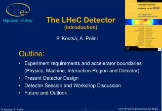
The LHeC Detector Project -Tracker Design http://cern.ch/lhec P.Kostka, A.Polini Meeting at University of Liverpool December 16, 2011 • Outline • Machine/Accelerators Concepts and constraints • Detector Requirements • Baseline and extended options • Detector Components • Tracking details and ideas
IP2 Accelerator Concept(s) LHeC Assuming that ep collisions take place at point IP2 which currently houses the ALICE experiment Add e∓ (polarised) on genuine p/A beams and running simultaneously with LHC program Ring-Ring (RR) Difficulties:building e ring into LHC tunnel,synchrotron radiation andlimitations of energy Electrons beam circulates in the existing LHC tunnel 5
Challenge: Bypassing the main LHC detectors The LHeC Ring-Ring Challenging: bypassing the main LHC Detectors IP2 e-injector is a 10 GeV sc linac in triple racetrack configuration 3
Linac-Ring (LR) THera (DESY) low interference with LHC,higher electron energy, lower lumi* at reasonable power IP2 *) currently - but may be improved The LHeC Linac-Ring LR: recirculating* linac with e∓ energy recovery, or straight linac *)bypassing own IP Add e∓ (polarised) on genuine p/A beams and running simultaneously with LHC program
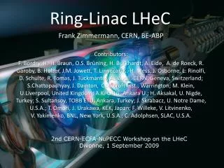
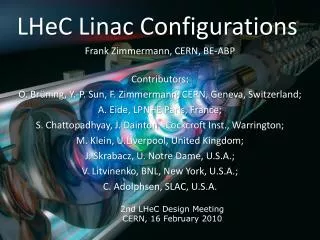
10 GeV 10, 30, 50 GeV 10 GeV Baseline Linac-Ring Option Super Conducting Linac with Energy Recovery & high current (> 6mA) Two 1 km long sc Linacs (10GeV) in cw operation (Q ≈ 1010) LR: less invasive with respect to the existing LHC, needs the construction of a new linear accelerator complex Relatively large return arcs ca. 9 km underground tunnel installation total of 19 km bending arcs same magnet design as for RR option: > 4500 magnets Oliver Brüning CERN EPS-HEP, 23 July 2011, Grenoble
3 beams, head‐on collisions Photon Number Density at the IP SR y [mm] p-beam 2 p-beam 1 x [mm] e-beam LR Interaction Region Special attention is devoted to the interaction region design, which comprises beam bending (in/out), direct and secondary synchrotron radiation, vacuum and beam pipe demands. • Dipoles around the IP (2 x 9m, 0.3T) make electrons collide head-on with p-beam 2 & safely extract the disrupted electron beam. • Simulation of Synchrotron Radiation (SR) load in the IR and design of absorbers / masks shielding SR from backscattering into the detector & from propagating with e± beam. • Beam pipe design - space for SR fan - tracking/calorimetry close to the IP / beam line (goal: 1°-179°)
Legend : Dipole ep ep RR Option - Beam & Fan Envelopes LR Option - Beam & Fan Envelopes x [mm] x [mm] Triplet Position z= ~10m Triplet Position z= ~22m z [mm] z [mm] LR, RR option - Beam & SR SR Fan growth with z SR Fan growth with z (high luminosity case)
LR - Inner Dimensions Circular(x)=2.2cm; Elliptical(-x)=-10., y=2.2cm y=2.2cm y=2.2cm x= -5.5cm x=2.2cm x= -10cm x=2.2cm Beam Pipe / Profile - SR Fan RR- Inner dimensions (masks at 6, 5, 4m - primary SR shield)Circular(x)=2.2cm (LHC upgrade); Elliptical(-x)=-5.5, y=2.2cmbeam pipe dimensions reduced - using static / movable masks; housing beam/SR envelopes + 1cm safety margin
100 10 IP RR Beam Optics and Detector Acceptance • High Acceptancefirst e beam magnet placed at z= ±6.2mL ~ 7.3 x 1032 cm-2 s-1 (1° < θ < 179°) • L ~ 1.3 x 1033 cm-2 s-1 (10° < θ < 170°)High LuminosityLow β* magnets near the IP (HERA2) (at z= ±1.2m) • Detector flexible accommodating both HA / HL(forward / backward tracker & calorimeter end-caps)RR: 1mrad crossing angle (25ns bunch spacing; avoiding parasitic interactions); LR: head on (but dipoles for beam separation over full detector length + beyond)Consequences on detector design: • RR Lower Lumi, Low Q2 access → High Acceptance detector 1° - 179° • RRHigher Lumi, High Q2 access → High Luminosity detector 10° - 170° aperture • ↕ factor ~ 2 only
Machine Options - Impacts • Linac-Ring (LR) • 2 x 9m 0.3 T dipole over full detector length (and beyond) • Ring-Ring (RR) • High Acceptance High Lumi option - low β-quadrupoles near to the Interaction Point→ Detector modular / removable forward / backward tracker & calorimeter end-caps • Beam Optics / Synchrotron Radiation • beam pipe circular-elliptical - aperture φ-dependent→ detector design - follow BP shape
The LHeC Detector Concept • High Precision resolution, calibration, low noise at low y, tagging of b,c;based on the recent detector developments, using settled technology, avoiding R&D programs. • Modular and flexibleaccommodating the HA/HL physics programs (RR); “Fast” detector assembly above ground; Detector access (shutdown). • Minimal radiation length tracker design: integrating services into support structure. • Small radius and thin beam pipe optimized in view of aperture(1-179o acceptance covering low Q2, high x physics program), synchrotron radiation and background production. • Affordable - comparatively reasonable cost.
Design Arguments • Electron • final state: high resolution for final states • DIS: precision calibration employing over-constrained kinematics 10%/ √E calibrated using the kinematic peak • acceptance: large angle acceptance to measure at low Q2 ≥ 1 GeV2 • Hadrons • jets: few TeV in forward direction • DIS: precision calibration of Eh (pth / pte balance at low y) 40%/√E (or better) calibrated with pth /pte to 1% accuracy • acceptance: measure hadronic energy down to few degrees • Heavy Flavour Physics • efficient c and b tagging towards large |ɳ| • Diffractive Processes and eD • forward tagging of p, n, d • accurate luminosity measurement (difficult) and efficient e/ɣ tagging in backward direction
e∓ p/A p/A dipole layout RR option only (no dipole) - High Acceptance Option studied also where the larger solenoid surrounds the hadronic calorimetry. Magnetic field outside the solenoid (3.5T) is ≈1.5T;Volume instrumented with 3 multilayers of muon chambers. Dimensions: about 11m length and 8m diameter. Detector Options - 1 dipole dipole LR detector - r-z plane dipole (radius ~0.6m, 0.3T) and solenoid (3.5T) placement between the electromagnetic and the hadronic calorimeters. The IP is surrounded by a central tracker system, large forward and backward tracker telescopes and sets of calorimeters. Detector dimensions z≈14m, diameter ∅≈9m.
Detector design - follow BP shape (CPT/CST shown) p/A p/A Linac-Ring - beam pipe inner-Rcirc=2.2cm inner-Relliptical=10.cm Main detector for the RR - luminosity maximised by low β quadrupole magnets The forward/backward tracking removed &the outer calorimeter inserts placed near to IP ( |1.2| m) Detector Options - 2 e∓ The baseline configuration (LR case). Central barrel: silicon pixel detector (CPT) silicon tracking detectors (CST,CFT/CBT) electromagnetic calorimeter (EMC) surrounded by the magnets (Solenoid, Dipoles) hadronic calorimeter (HAC) Backward silicon tracker (BST) energy measured in the BEC and BHC calorimeters Forward silicon tracking (FST) and calorimetry (FEC, FHC) measuring TeV energy final states For numeric studies and plots see recent talks atDIS10, DIS11, ICHEP10, EPS11, IPAC11, …EIC and LHeC Workshopsat http://cern.ch/lhec
BST - ΔZ=8. cm min-inner-R = 3.1 cm; max-inner-R= 10.9 cm outer R = 46.2 cm Planes 1 - 3: z1-3 = -130. / -170. / -200. cm FST - ΔZ=8. cm min-inner-R = 3.1 cm; max-inner-R= 10.9 cm outer R = 46.2 cm Planes 1 - 5: z5-1 = 370. / 330. / 265. / 190. / 130. cm Central Si Tracker Central Pixel Tracker • CST - ΔR 3.5cm each • 1. layer: inner R = 21.2 cmlayer: = 25.6 cm • 3. layer: = 31.2 cm4. layer: = 36.7 cm5. layer: = 42.7 cm 4 layerCPT min-inner-R= 3.1 cm max-inner-R = 10.9 cm ΔR =15 cm Central Forward/Backward Tracker 4 CFT/CBT min-inner-R = 3.1 cm, max-inner-R= 10.9 cm Electromagnetic Calorimeter Forward Si Tracker Backward Si Tracker Tracking - High Acceptance • Dominant forward production of dense jets; backward measurements relaxed
1.4 8.1 1.8 1.8 3.3 2.0 Tracker Dimensions
LicToy 2.0 Simulation - Simplified Geometry Tracker Simulation http://wwwhephy.oeaw.ac.at/p3w/ilc/lictoy/UserGuide_20.pdf
Tracking - Pixel • Tracker technology … available today ! • Modularstructure for replacement / maintenance and detector adoption: RR high luminosity / high acceptance running • Pixel Detector*) ( CPT 1-4 )barrel pixel (1.4m2 sensor area - hybrid single plane Si, overlaps incl. )→ sensor & R/O electronic bump bonded.n-in-p ( sLHC ) or n+-in-n (2-3x more expensive) - CMS / ATLAS / LHCb CPT 1-4 - 50µm x 250µm pixel size ( FE-14 - ATLAS ) or 100µm x 150µm (ROC - CMS) • Part of FST - pixel equipped - for Θ ≤ 4° ? Decision on inner radius FST blade equipement after detailed radiation - /track density simulation (being prepared - FLUKA/GEANT4). • Lowpower consum. & lownoise & “easy”handling & ASICs available *) discussed by N.Wermes (1st CERN-ECFA Workshop on the LHeC - 2008): Silicon Pixel detectors for Tracking;R.Horrisberger (CMS Tracker Week La Biodola, Isola d’ Alba - 2010: Tracking at Phase II - Pixel, Strixel & Strips;P.Allport (3rd CERN-ECFA-NuPECC Workshop on the LHeC - 2010: “Conventional” Silicon Pixel/Strip Tracker; …
Material Reduction (ATLAS Upgrade) P.Allport (3rd CERN-ECFA-NuPECC Workshop on the LHeC - 2010: “Conventional” Silicon Pixel/Strip Tracker
Central Tracking - Strip • CST - 5 barrel layer strip (13.1 m2 sensor area) → sensor & R/O electronic wire bonded • 100µm pitch, 5cm strip length • “Two-in-One” Strip - Modules - CMS: • Cost of a normal TOB module (~40 CHF/cm2) → extra Si-sensor < +8 CHF/cm2) • “Two-In-One” TOB modules can be configured as pt-triggering or stereo layers • Connectivity for upper to lower sensor signals solved with no extra power • Low mass construction by double use of hybrid infrastructure (power, cooling, . .) • Wire-bond construction very conventional and simple → technology at hand • Low power pt-signal correlation due to local neighbour channel communication • CBC short Strip ROC with binary signals would be perfect for this job. Roland Horrisberger (PSI), CMS Tracker Week La Biodola, Isola d’ Alba - 2010: Tracking at Phase II - Pixel, Strixel & Strips
12.8mm “Two-In-One”Design as Stereo modules (top view) ROC’s 256 channel 50μ input pitch top Silicon sensor bottom Silicon sensor hybrid stereo angle ~ 10-20mrad 5cm strips. 100μ pitch ~7.6 cm 10 cm Varying wire bonding length ~ 300 – 600 μm Roland Horrisberger (PSI), CMS Tracker Week La Biodola, Isola d’ Alba - 2010: Tracking at Phase II - Pixel, Strixel & Strips
Forward/Backward Tracking - Strip • FST / BST - 5 / 3 disk strip (2x5.3 m2 - sensor layer area) → sensors & R/O electronic wire bonded Part of FST - pixel equipped (?) - possible for Θ ≤ 4° Decision on inner radius FST blade equipement after detailed radiation & track density simulation. • 100µm pitch, 5cm strip length • “Two-in-One” Strip - Modules for CST
179◦ 20◦ 10◦ 90◦ 1◦ 170◦ 170◦ 179◦ LHeC Kinematics High x and high Q2: few TeV HFS scattered forward: Need forward calorimeter of few TeV energy range down to 10o and below █.Mandatory for charged currents. Strong variations of cross section at high x demand hadronic energy calibration as good as 1% Scattered electron: need very bwd angle acceptance for accessing low x and Q2 █.
CAD - GEANT4 Interfacing • https://code.google.com/p/cadmesh/ • Importing predefined CAD models into GEANT4is not always possible or requires intermediate file format conversion to Geometry Description Markup Language (GDML) using commercial or third party software. • CADMesh is a direct CAD model import interface for GEANT4 leveraging VCGLIB. Currently it supports the import of triangular facet surface meshes defined in formats such as STL and PLY. A G4TessellatedSolid is returned and can be included in a standard user detector constructor. • Need for fast, reliable transformation procedure (both directions)see: http://arxiv.org/abs/1105.0963, 5 May 2011
n-in-p • ~50% less expensive than n-in-n • Single-sided processing • More suppliers (including Hamamatsu) • Limited production experience • 1 VELO module installed, spare system under construction • As radiation hard as n-in-n • n+ R/O kept ATLAS Pixel Module Upgrade • n-in-n • Most expensive • Double-sided processing • Limited suppliers • Some experience with “large” scale production • CMS/ATLAS pixels, LHCb VELO • Much more radiation hard than p-in-n n-in-p n-in-n Silicon sensor Bias Ring Bias Ring Guard Ring Guard Ring SiO2 Readout chip SiO2 n+ n+ p-spray/stop p-spray/stop • Hybrid pixel detector: • The sensor and the readout electronic are realized in different semiconductor substrates • Size of the electronic readout pixels is equal to the size of the sensor pixels • The connection between the electronic and the sensor is done via bump bond connections Bump bond connection n- bulk p- bulk p+ p+ Al Al Bias Ring Guard Ring P.Allport, 3rd CERN-ECFA-NuPECC Workshop on the LHeC - 2010: “Conventional” Silicon Pixel/Strip Tracker
CMS Single-Sided (n-in-p) Sensors n-in-n • Present CMS pixel detector uses n-in-n-sensors • double sided processing (back side is structured) • all sensor edges at ground • most expensive part of the module (only bump-bonding is more expensive) • Exploring n-in-p sensors as alternative • recent studies show radiation hardness • single sided process promise price benefit of factor 2-3 • important as the pixel area will be doubled • Absence of guard rings on back side lead to fear of (destructive) sparking to the ROC n-in-p T. Rohe et al. Planar sensors for the upgrade of the CMS pixel detector, Pixel2010, Sep. 6-10, Grindelwald, CH
Pt - Trigger for TOB layers “Two-In-One” Design 50mm strips 2mm 2 x DC coupled strip detectors SS, 100μ pitch < 8CHF/cm2 wire bonds Strip Read Out Chip 2 x 100μ pitch with on-chip pt-correlator 2mm spacer 1mm track angular resolution ~20mrad good Pt resolution W. Erdmann &Roland Horrisberger (PSI), CMS Tracker Week La Biodola, Isola d’ Alba - 2010: Tracking at Phase II - Pixel, Strixel & Strips.
Pixel ROC based strixel readout • 2x16 ROC / module CCA – power & readout cables μ-twisted pairs Pixel TBM chip Hybrid 110 mm 64 strixels at 1.75mm pitch Sensor Area = 43 cm2 38.4mm 1024 strixels at 75μ pitch Strixel TIB Layers C-fibre 260μ thick “Toblerone” structure shell stiffness face up Strixel module face down CO2 cooling pipes Strixel module face down W. Erdmann &Roland Horrisberger (PSI), CMS Tracker Week La Biodola, Isola d’ Alba - 2010: Tracking at Phase II - Pixel, Strixel & Strips.