Download
1 / 10
100 likes | 132 Views
This article provides a review of TDD beam measurement operations in 802.11ay MAC, focusing on gaps and improvements for non-AP devices. It discusses the drawbacks of proprietary network controllers and proposes solutions for standardized data and management planes.

E N D
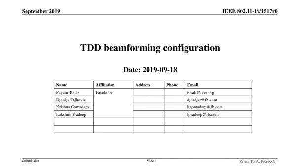
TDD beamforming configuration Date: 2019-09-18 Payam Torab, Facebook
TDD beamformingBackground • TDD beamforming operations other than Initial Beamforming* are referred to as Beam Measurement in the standard • Before Draft 4.0, these operations were exclusively initiated by (and results reported to) SME • Requiring connection to (proprietary) network controller • For client devices (non-AP STAs) connection to (proprietary) controller is undesirable • Proprietary connection (software) impedes commercialization • We review some TDD beam measurements operations for some gaps Payam Torab, Facebook
TDD beamformingBackground Proprietary Network Controller • Before Draft 4.0 • Standard 802.11ay MAC plus some proprietary functions • DNs and CNs requiring proprietary software • Improvement • Standard 802.11ay MAC including standard management functions • DNs requiring proprietary software • CNs 60 GHz operation entirely specified by 802.11 (no need for proprietary software) Proprietary management port Proprietary management port Proprietary Proprietary Management Proprietary Management 802.11ad|ay MAC Standard 802.11ad|ay MAC 802.11ad PHY Standard 802.11ad PHY DN (AP) CN (non-AP) Proprietary Network Controller TDD Sector Config Proprietary management port CN with standardized data plane and management plane Standard 802.11 Management 802.11 Management 802.11ad|ay MAC Standard 802.11ad|ay MAC 802.11ad PHY Standard 802.11ad PHY DN (AP) CN (non-AP) Payam Torab, Facebook
Example -- Periodic beamforming (PBF) Initiator MLME (and TDD Sector Config fields) • Start time • Period P or schedule (already provided) • TDD SSW multiplicity (Note 3) • Set of Rx beams (Note 4) Non-AP (CN) can also be the initiator Can be locally decided by non-AP, or administered through the AP/controller • Decided by non-AP: Send up the request (same arguments minus the schedule), get acknowledgement, schedule, start time (exchange of TDD Sector Config subelement) • Decided by AP: Same as runtime Rx calibration, except Tx beam selection is left to non-AP (see the runtime Rx calibration slide) Example implementation • Initiator transmitting on different Tx beams during beamforming slot every 400 µs, cycling through all Tx beams (Note 1) • Transmission pattern repeated 31 times, with responder measuring on a different receive beam during each transmit cycle • Responder reporting the result through the controller Notes • Equivalent to an 802.11ad I-TXSS (directional receive) • Some or all of Tx beams can be the same, e.g., for averaging • Knowing the TDD SSW multiplicity can help with averaging decisions • Set of Rx beams can be null to leave the Rx selection to responder Generalized • Initiator trying Ntx transmit beams against Nrx responder’s receive beams, during periodic or irregular (but scheduled) beamforming slots (Nrx = 1 for current implementation) • Initiator trying a generally different Tx Beam at every new Beamforming slot (taking Ntx slots for Tx sweep) (Note 2) • Responder receiving on each Rx beam Ntx times, so it can try them against all different Tx beams • Start time pointing to start of the first beamforming slot used for operation; schedule assumed consistent with beamforming pattern and duration • Allow TDD SSW Feedback and TDD SSW Ack, with option to skip • Responder sends SNR report to initiator through TDD Route IE (TDD Sector Feedback subelement) • Initiator does not send a SNR report Payam Torab, Facebook
Example – Transmit beam calibration Initiator MLME (and TDD Sector Config fields) • Start time • Period P or schedule (already provided) • TDD SSW multiplicity (Note 3) • Set of Rx beams (Note 4) Non-AP (CN) can also be the initiator Can be locally decided by non-AP, or administered through the AP/controller • Decided by non-AP: Send up the request (same arguments minus the schedule), get acknowledgement, schedule, start time (exchange of TDD Sector Config subelement) • Decided by AP: Same as runtime Rx calibration, except Tx beam selection is left to non-AP (see the runtime Rx calibration slide) Example implementation • Initiator transmitting on generally different Tx beams during beamforming slot every 400 µs (Note 1, 2) • Responder measuring signal in corresponding beamforming slots using the current Rx beam • Responder reporting the result through the controller Notes • Equivalent to an 802.11ad I-TXSS (directional receive) • Some or all of Tx beams can be the same, e.g., for averaging • Knowing the TDD SSW multiplicity can help with averaging decisions • Set of Rx beams can be null to leave the Rx selection to responder Generalized • Initiator trying Ntx transmit beams against Nrx responder’s receive beams, during periodic or irregular (but scheduled) beamforming slots (Nrx = 1 for current implementation) • Initiator trying a generally different Tx Beam at every new Beamforming slot (taking Ntx slots for Tx sweep) (Note 2) • Responder receiving on each Rx beam Ntx times, so it can try them against all different Tx beams • Start time pointing to start of the first beamforming slot used for operation; schedule assumed consistent with beamforming pattern and duration • Allow TDD SSW Feedback and TDD SSW Ack, with option to skip • Responder sends SNR report to initiator through TDD Route IE (TDD Sector Feedback subelement) • Initiator does not send a SNR report Payam Torab, Facebook
Example – Rx Beam calibration Initiator MLME (and TDD Sector Config fields) • Start time • Period P or schedule (already provided) • TDD SSW multiplicity (Note 3) • Set of Tx beams (Note 4) Non-AP (CN) can also be the initiator Can be locally decided by non-AP, or administered through the AP/controller • Decided by non-AP: Send up the request (same arguments minus the schedule), get acknowledgement, schedule, start time (exchange of TDD Sector Config subelement) • Decided by AP: Same as runtime Tx calibration, except Rx beam selection is left to non-AP (see the runtime Tx calibration slide) Example implementation • Initiator trying generally different Rx beams during each beamforming slot every 400 µs (Note 1, 2) • Responder transmitting TDD SSW frames in corresponding beamforming slots on the current Tx beam • Initiator reporting the result through the controller Notes • Equivalent to an 802.11ad I-RXSS • Some or all of Rx beams can be the same, e.g., for averaging • Initiator specifying the TDD SSW multiplicity to control averaging decisions • Set of Rx beams can be null to leave the Rx selection to responder Generalized • Initiator trying Nrx receive beams against Ntx responder’s transmit beams, during periodic or irregular (but scheduled) beamforming slots (Ntx = 1 for current implementation) • Initiator trying a generally different Rx Beam at every new Beamforming slot (taking Nrx slots for Rx sweep) (Note 2) • Responder transmitting on each Tx beam Nrx times, so initiator can try them against all different Rx beams • Start time pointing to start of the first beamforming slot used for operation; schedule assumed consistent with beamforming pattern and duration • Allow TDD SSW Feedback and TDD SSW Ack, with option to skip • No SNR report exchanged Payam Torab, Facebook
Example – Interference measurement Initiator or AP MLME (and TDD Sector Config fields) • Start time • Period P or schedule (already provided) • TDD SSW multiplicity (Note 3) • Set of responders • Set of Rx beams (Note 4) • TA address (Note 5) Non-AP (CN) can also be the initiator Can be locally decided by non-AP, or administered through the AP/controller • Decided by non-AP: Send up the request (same arguments minus the schedule, plus list of responders (e.g., some of RAs that have been received), get acknowledgement, schedule, start time (exchange of TDD Sector Config subelement) • Decided by AP or another STA outside BSS (request coming to AP through the controller): MLME/AP config parameters above Example implementation • Initiator transmitting on generally different Tx beams during beamforming slot every 400 µs (Note 1, 2) • Broadcast RA for TDD SSW frames • Multiple responders measuring signal in corresponding beamforming slots using their current Rx beams • With invert scan polarity measurement slots are sometimes scheduled in the Tx subframe (i.e., where the device is normally expected to transmit) (supported by Slot Schedule IE general format, no standard change needed) • Responders reporting the result through the controller • Any device can be the initiator (DN or CN) • No notion of BSS association for different responders (network-level operation) Notes • Sweep can be repeated (is ended administratively) • Some or all of Tx beams can be the same, e.g., for averaging • Responder knowing the TDD SSW multiplicity can help with averaging decisions • Set of Rx beams can be null to leave the Rx selection to responder • TDD Sector Config exchange for another TA not in BSS Generalized • Number of beamforming slots in the schedule given to initiator does not have to be a multiple of number of scanned Tx beams • For example, 100 slots may be allocated for interference scan using 31 Tx beams • Different responders schedules (and obviously Rx beams)(this is more generalizing the procedure than generalizing any protocol) • For example, one responder scanning during a portion of the 100 slots in the above example, while another responder scanning during the entire 100 slots Payam Torab, Facebook
Coordinated beamforming – Transmit training Generalized • Number of beamforming slots in the schedule given to initiator does not have to be a multiple of number of scanned beams • For example, 100 slots may be allocated to scan 31 Tx beams • Different receive schedules (and Rx beams) for each victim link (this is more generalizing the procedure than generalizing the protocol) • For example, one responder receiving during a portion of the 100 slots in the above example, while another responder receiving during the entire 100 slots Initiator or AP MLME (and TDD Sector Config fields) • Start time • Period P or schedule (already provided) • TDD SSW multiplicity (Note 3) • Set of responders • Set of Rx beams (Note 4) • TA address (Note 5) Non-AP (CN) can also be the initiator Probably can be administered through the AP/controller only (under study) Example implementation • Network level interference nulling operation involving an aggressor link and multiple victim links: Finding the Tx beam with least interference to multiple victims • Initiator (on aggressor link) transmitting on generally different Tx beams during beamforming slot every 400 µs (Note 1, 2) • Multiple responders (on multiple victim links) receiving on a given Rx beam during beamforming slots allocated to them (with invert scan polarity sometimes this may happen in the opposite subframe) • Responders reporting the result through the controller • Any device can be the initiator (DN or CN) • No notion of BSS association for different responders (network-level operation) • Notes • Sweep can be repeated (is ended administratively) • Some or all of Rx beams can be the same, e.g., for averaging • Knowing the TDD SSW multiplicity can help with averaging decisions • Set of Rx beams can be null to leave the Rx selection to responder • TDD Sector Config exchange for another TA not in BSS • Operation is runtime Tx calibration on aggressor (responders receiving on constant receive beams) + TA filtering Aggressor link ATX (initiator) ARX VTX1 Victim link 1 VRX1 VTX2 Victim link 2 VRX2 Payam Torab, Facebook
Coordinated beamforming – Rx training (Rx CBF) Generalized • Number of beamforming slots in the schedule given to initiator does not have to be a multiple of number of scanned beams • For example, 100 slots may be allocated to scan 31 Rx beams • Different transmit schedules (and Tx beams) for each aggressor link (this is more generalizing the procedure than generalizing the protocol) (Note 7) • For example, one responder transmitting during a portion of the 100 slots in the above example, while another responder transmitting during the entire 100 slots Initiator or AP MLME (and TDD Sector Config fields) • Start time • Period P or schedule (already provided) • TDD SSW multiplicity (Note 3) • Set of responders • Set of Rx beams (Note 4) • TA addresses (Note 5) Non-AP (CN) can also be the initiator Probably can be administered through the AP/controller only (under study) Example implementation • Network level interference nulling operation involving multiple aggressor links and a victim link: Finding the Rx beam with least interference from multiple aggressors • Initiator (on victim link) receiving on generally different Rx beams during beamforming slot every 400 µs (Note 1, 2) • Multiple responders (on multiple aggressor links) transmitting on a given Tx beam during beamforming slots allocated to them (with invert scan polarity sometimes this may happen in the opposite subframe) • Initiator reporting the result through the controller • Any device can be the initiator (DN or CN) • No notion of BSS association for different responders (network-level operation) • Notes • Sweep can be repeated (is ended administratively) • Some or all of Rx beams can be the same, e.g., for averaging • Knowing the TDD SSW multiplicity can help with averaging decisions • Set of Rx beams can be null to leave the Rx selection to responder • TDD Sector Config exchange for other TAs not in BSS • Operation is runtime Rx calibration on victim (responders transmitting on constant transmit beams) + TA filtering • Interference measurement with simultaneous transmission is problematic – 802.11ad/ay directional channel measurement (ANIP and RSNI) with TDD extensions may be applicable Victim link VTX VRX (initiator) ATX1 Aggressor link 1 ARX1 ATX2 Aggressor link 2 VRX2 Payam Torab, Facebook
Next stepEnhancing the TDD Sector Config subelement • Add more information about • Sweeping pattern/schedule • Information from outside the BSS • For example, list of aggressor TA addresses during Rx CBF Payam Torab, Facebook