Download
1 / 21
220 likes | 318 Views
Explore magnetic field sources, Ampère’s Law, Biot-Savart Law, electromagnets, and more. Understand calculations and applications of magnetic fields.

E N D
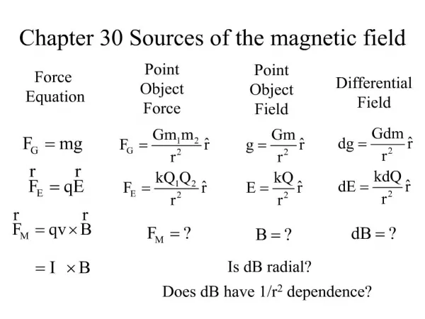
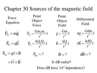
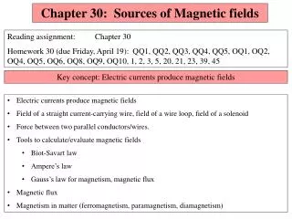
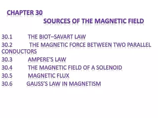
Chapter Outline • Magnetic Field Due to a Straight Wire • Force between Two Parallel Wires • Definitions: The Ampere& the Coulomb • Ampère’s Law • Magnetic Field of a Solenoid & of a Toroid. • Biot-Savart Law • Magnetic Materials – Ferromagnetism • Electromagnets and Solenoids – Applications • Magnetic Fields in Magnetic Materials; Hysteresis • Paramagnetism and Diamagnetism
Note! We’ll cover topics in Ch. 30 in a different order than your textbook! • Specifically, there are 2 main (equivalent) methodsto calculate magnetic fields. • These are the Biot-Savart Law& Ampère’s Law. • We’ll cover Ampère’s Law followed by the Biot-Savart Law. This is the opposite orderthan is in the textbook.
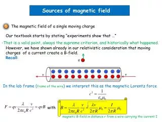
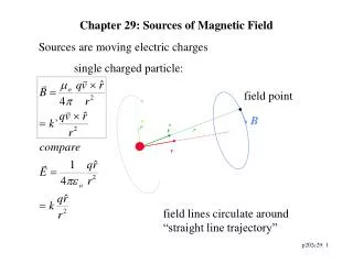
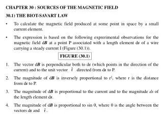
Magnetic Field Due to a Long, Straight Current Carrying Wire: Direction • Ch. 29: The magnetic field lines for a long, straight, current carrying wire are circles concentric with the wire. • The field lines are in planes perpendicular to the wire. • The magnitude of the field is constant on a circle of radius a. • Use the right-hand rule to determine the • direction of the field, as shown.
Magnetic Field Due to a Current Carrying Wire • A compass can be used to detect the magnetic field. • When there is no current in the wire, there is no field due to the current. • In this case, the compass needles all point toward the Earth’s north pole. This is due to the Earth’s magnetic field
Magnetic Field Due to a Current Carrying Wire • When the wire carries a current, the compass needles deflect in a direction tangent to the circle. • This shows the direction of the magnetic field produced by the wire. • If the current is reversed, the direction of the needles also reverses.
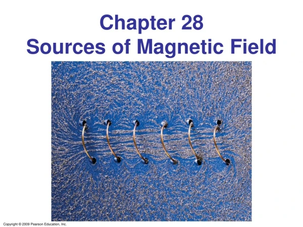
The circular magnetic field around the wire is shown by the iron filings.
Magnetic Field Due to a Straight Wire • Experimental Results show that the • Magnetic field Bdue to a straight, • current carying wire is proportional • to the Current I & inversely • proportional to the distance r from • the wire: • μ0is a constant, called the permeability • of free space. It’s value is • μ0 = 4π 10-7T·m/A. • It plays a similar role for magnetic • fields that ε0 plays for electric fields!
Calculation of B Near a Wire • An electric wire in the wall of a • building carries a dc current • I = 25 A vertically upward. • Calculate the magnetic field B • due to this current at a point • P = 10 cm in the radial • direction from the wire.
Calculation of B Near a Wire • An electric wire in the wall of a • building carries a dc current • I = 25 A vertically upward. • Calculate the magnetic field B • due to this current at a point • P = 10 cm in the radial • direction from the wire. • Solution • Use • This gives B = 5.0 10-5 T
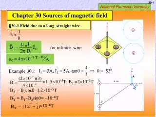
Example • Magnetic Field Midway Between Two Currents. • Two parallel straight wires a distance 10.0 cm apart carry • currents in opposite directions. Current I1 = 5.0 A is out • of the page, & I2 = 7.0 A is into the page. • Calculate the magnitude & direction of the magnetic • field halfway between the 2 wires.
Example • Magnetic Field Midway Between Two Currents. • Two parallel straight wires a distance 10.0 cmapart • carry currents in opposite directions. Current I1= 5.0 A • is out of the page, & I2 = 7.0 A is into the page. • Calculatethe magnitude & direction of the magnetic • field halfway between the 2 wires. • Solution: • Use • for each wire. Then • add them as vectors • B = B1 + B2 • B = 4.8 10-5 T
Conceptual Example • Magnetic Field Due to 4 Wires • The figure shows 4 long parallel wires carrying equal currents • into or out of the page. In which configuration, (a) or (b), is • the magnetic field greater at the center of the square? b a a a a
Conceptual Example • Magnetic Field Due to 4 Wires • The figure shows 4 long parallel wires carrying equal currents • into or out of the page. In which configuration, (a) or (b), is • the magnetic field greater at the center of the square? b a
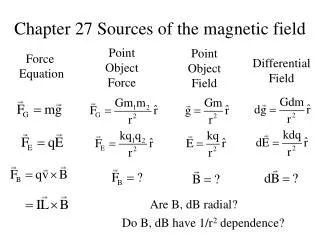
Magnetic Force Between Two Parallel Wires • Recall from Ch. 29 that the force F • on a wire carrying current I in a • magnetic field B is: • We’ve just seen that the magnetic • field B produced at the position of • wire 2 due to the current in wire 1 is: The magnetic force between 2 currentsis analogous to the Coulomb electric force between 2 charges!! • The force F this field exerts • on a length ℓ2 of wire 2 is
Using the cross product • form of the force: • & applying the right • hand rule shows that Parallel Currents ATTRACT and Anti-Parallel Currents REPEL.
ExampleForce Between Two Current-carrying Wires. • The two wires of a 2.0-m • long appliance cord are • d = 3.0 mm apart & carry • a current I = 8.0 A dc. • Calculate the force one • wire exerts on the other.
ExampleForce Between Two Current-carrying Wires • The two wires of a 2.0-m • long appliance cord are • d = 3.0 mm apart & carry • a current I = 8.0 A dc. • Calculate the force one • wire exerts on the other. • Use: • Resulting in • F = 8.5 10-3 N
Example • Suspending a wire with a current. • A horizontal wire carries a current I1 = 80 A dc. • Calculatethe current I2 that a second parallel wire d = 20 • cmbelow it must carry so that it doesn’t fall due to gravity. • The lower wire has a mass per meter of (m/ℓ) = 0.12 g/m.
Definition ofthe Ampere • The SI unit of current,the Ampereis officially • defined in terms of the force between two current • carrying wires: • One AmpereIS DEFINED as that current flowing in each of two long parallel wires 1 mapart, which results in a force ofexactlyF =2 10-7 Nper meterof length of each wire.
Definition ofthe Coulomb • Given that definition of the Ampere • One Coulombis IS DEFINED as exactly • 1 Ampere-second.