
Basic Electronics: Understanding Components & Circuits
E N D
Presentation Transcript
Basic electronics By: Andrew DeFino
Components we will cover • Resistor • Potentiometer • Diode • LED (Light Emitting Diode) • Capacitor • Breadboard • Jumper Wire • Momentary Push Button • Transistor • Integrated Circuit
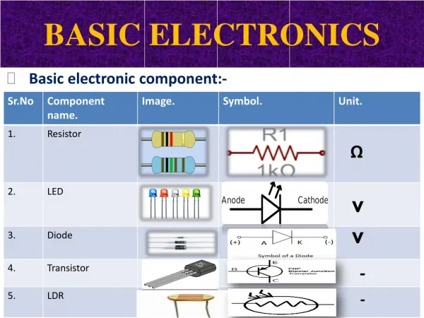
Resistor • Resists the flow of electricity • The color bands indicate its resistance • Resistance is measured in Ohms (Ω) • The last band is its tolerance. In other terms, the ranges of values it could be if not the given value • The most common tolerance band colors is Gold and Silver • Bi-directional, meaning you can place either side on positive or negative
How to Find the Resistor's Value Read it from left to right, with the tolerance band on the right-hand side Get the value of the first band Get the value of the second band Put those two values together Get the value of the third band Multiple the numbers from step 3 and 4 State the tolerance Red, 2 Black, 0 Together: 20 Multiplier: 100 2,000Ω Tolerance of 5%
Potentiometer • Acts as a resistor that you can change the value of • You just turn the knob to change the value between the minimum and maximum
Diode • Allows electricity to pass in only one direction • The side with the silver band gets connected to negative • Negative is also known as Cathode, while positive is the Anode
LED • Works just like a Diode, except it will also emit light • There is also RGB LEDs that have multiple colors all in a single package, which has four leads • The negative wire is shorter than the positive lead • Failing that, the negative side of the LED is slightly flat
Capacitor • Stores a small amount of energy • They are often used to stabilize voltage, whichmakes a clean signal for devices • The side with the white band is negative • There are two main types, Ceramic (Left), and Electrolytic (Right) • Ceramic stores less power
Breadboard • Provides a convenient way to easily make circuits • The pair of long ‘rails’ on each side is used for power connections • For most breadboards, the holes are connected in two rows of 5, with a gap in the middle • The gap is used to connect chips onto the board without their pins interfering with each other
Jumper Wires • A plain wire connecting two electric paths together on a breadboard • Comes in different sizes and colors • The different colors are useful for color coding your circuit
Momentary Push button • Usually just called a button • The pins on the same side DO NOT connect without pressing the button • While the corresponding pin on the other side DOES connect without pressing the button • Pressing the button connects these two sides together
Transistor • The basic part of all modern computers • Transistors are an electronic switch that have three pins: Input, Control, and Output • When the control is on, the input can pass to the output • There is two types of transistors, both have their peculiarities and specialized uses, like amplifying signals
Integrated Circuit • Provides complex features for circuits in a very small and robust package • Each IC (Integrated Circuit) has a small notch on one side to indicate which pins are which • The first pin on the left of the notch is number one, and then goes down the side, and jumps across and to the other side and heads back up to the notch
Name the parts • Jumper Wire • Integrated circuit • Diode • Resistor • Transistor • LED • Capacitor
Circuit Schematics • They are designs of circuits, complete with every part and its value • Each component is represented by a symbol with lines (Wires) leading into/out of it
Circuit Schematic Parts • <- Diode / LED • The LED has arrows coming off from it, signifying light
Making a Dimming LED • Parts • 1KΩ Resistor • Potentiometer • White LED • 9 Volt Battery and connector
Dimming Circuit • Explanation • The power goes into the middle pin of the potentiometer, and then exits from the right side • Based on the value of the potentiometer, it will resist some current flowing through • The power then goes through the LED, which emits light • Lastly, the final resistor is there to prevent the LED from burning out when the potentiometer is fully on
Making a dual LED toggle circuit • Parts • 100Ω Resistor • 330Ω Resistor • Diode • Two Blue LEDs • Two pushbuttons • 9 Volt battery and connector
Double LED circuit • Explanation • There are two paths the circuit has, in the first (The right button) • The resistor is 330Ω, which allows the battery to power the LED without it burning out. • Then it goes on to a push button switch that connects to a single LED, and then the negative terminal of the battery. • The second path: • Goes through a 100Ω resistor, so the battery can power both LEDs. • Then there is a push button for this side of the circuit too. • After the button, it leads to the first LED, then a diode, and then the second LED.
Double LED Circuit Improvements • The LED itself is a diode, therefore, a separate diode is not needed. • Instead of having the resistor flow to both LEDs, the first LED heads right into the other. • This makes both LED have the same brightness, due to the energy flowing through them equally now.
Thank you Stay tuned for more tutorials and workshops from the BSU Makerspace!