Download
1 / 18
180 likes | 275 Views
Detailed study of gas amplification devices in a magnetic field for TPC measurements. Collaboration between Cornell University, Purdue University, and LC-TPC. Supported by NSF and DOE grants.

E N D
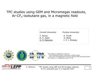
TPC studies using GEM and Micromegas readouts, Ar-CF4-isobutane gas, in a magnetic field Cornell University Purdue University T. Anous K. Arndt R. S. Galik G. Bolla D. P. Peterson I. P. J. Shipsey This project is supported, in part, by the US National Science Foundation (LCDRD award) and by the US Department of Energy (Purdue HEP group base grant). This project is in collaboration with LC-TPC. D. Peterson “TPC studies using GEM and Micromegas readouts, Ar-CF4-isobutane gas, in a magnetic field”
in this talk … measurements using the small prototype TPC at Cornell triple-GEM(standard) B=0, 1.0, 1.45 Tesla, T2K gas:Ar-CF4-isobutane 95:3:2 bulk Micromegas B=0, 1.0, 1.45 Tesla, T2K gas for calibration triple-GEM B=1.0, TDR gas: Ar-CH4-CO2 93:5:2 same chamber, gas, magnetic field, pad geometry, readout, analysis unfortunately, different gain. D. Peterson “TPC studies using GEM and Micromegas readouts, Ar-CF4-isobutane gas, in a magnetic field”
14.6 cm ID field cage - accommodates a 10 cm gas amplification device 64 cm drift field length 22.2 cm OD outer structure (8.75 inch) HV is separately controlled on the cathode (20kV max) , field cage termination, gas amplification device. Voltage distribution differs from others; ground is at the end of the drift field, allowing independent control of the gas amplification. Readout is 88 channels, Struck FADC, 105 MHz (run at 25 MHz), circular buffer 14 bit, +/- 200 mV input (least count is 25 μV) D. Peterson “TPC studies using GEM and Micromegas readouts, Ar-CF4-isobutane gas, in a magnetic field”
The CLEO magnet… 1.5 Tesla, 1 meter radius, 2 meter length July 2008, removed the tracking chambers and RICH from the CLEO magnet installed small prototype TPC, and trigger scintillators with room to spare. D. Peterson “TPC studies using GEM and Micromegas readouts, Ar-CF4-isobutane gas, in a magnetic field”
at near right: TPC and Trigger scintillator geometry 3 scintillators, 4.6cm square at far right: Pad geometry 9 layers 4 layers have 2mm x 10 mm cells 5 layers have 5mm x 10mm cells two tracks that satisfy the trigger: 1) straight, with TAN(θ)=0.1 2) diameter=1.6 meter P=348 MeV/c at 1.45Tesla (minimum momentum) Measurements of the charge-width include a contribution from the track angle, distributed within the acceptance. This is simply corrected/subtracted. Other complications are not so simple. D. Peterson “TPC studies using GEM and Micromegas readouts, Ar-CF4-isobutane gas, in a magnetic field”
Measurement of the point-resolution is complicated by the use of large (2mm) pads, coupled with narrow charge-width. Resolution measurements are based on differences of residuals with respect to a track fit. Note that this sample track, with TAN(θ)=0.1, can satisfy charge-sharing in pairs of layers , even with a charge-width of zero. With small charge-width, and requiring charge-sharing, tracks will be selected, biased to this track angle. When charge is shared, it is spread over only 2 pads. “Precision” measurements require knowledge of the charge-width-dependent, non-linear mapping, from the charge-center-position to the charge-sharing. This will be described later. (slide 10) The charge-width, used in the mapping above, must include the contribution from the track angle projected onto the pads, applied track-by-track. D. Peterson “TPC studies using GEM and Micromegas readouts, Ar-CF4-isobutane gas, in a magnetic field”
Measurement of the point-resolution is further complicated by the limited number of 2mm pad layers. The track fit is to a straight line. The resulting error in the residual difference was calculated for tracks within the phase space of accepted tracks. The contribution to the point resolution width, from using a fit to a straight line is σ ~102 μm. Understanding the corrections to the measurements, there is still a chance of extracting the inherent charge width and point resolution. D. Peterson “TPC studies using GEM and Micromegas readouts, Ar-CF4-isobutane gas, in a magnetic field”
Measurements with 2 gas-amplification devices. The Micromegas is a 50μm bulk prepared by LCTPC collaborators at Saclay The triple-GEM is standard CERN GEMs prepared by colleagues at Purdue. D. Peterson “TPC studies using GEM and Micromegas readouts, Ar-CF4-isobutane gas, in a magnetic field”
Micromegas T2K gas, Ar-CF4-isobutane 95-3-2, Edrift=150V/cm Micromegas voltage: 350 V Gain is 2.15 x 10⁴ (Paul Colas) The gain was constant from B=0 to 1.45 Tesla, 105 counts GEM T2K gas, Ar-CF4-isobutane 95-3-2, Edrift=150V/cm GEM voltages: 235, 235, 239 V transfers fields: 1.65 mm, 1540V/cm 1.65 mm, 1550V/cm 1.65 mm, 1454V/cm induction At B=0, the gain was set to be 1.10 x the gain of the Micromegas. At B=1.0 and 1.45 Tesla, the gain increased by 1.71, is 1.88 x the gain of the Micromegas. ) TDR gas, Ar-CH4-CO2 93:5:2, Edrift=220V/cm GEM voltages: 315, 315, 315 V transfers fields: 1.65 mm, 2060V/cm 1.65 mm, 2060V/cm 1.65 mm, 1930V/cm induction At B=1 Tesla, the gain is 1.35 x the GEM with T2K gas setting, 2.5 x the Micromegas with T2K gas. D. Peterson “TPC studies using GEM and Micromegas readouts, Ar-CF4-isobutane gas, in a magnetic field”
A particular charge-width results in a non-linear response of charge-sharing, w.r.t. charge position. A family of curves for various values of charge-width. Each results in an average charge-sharing. Plot the average charge-sharing, w.r.t. charge-width. This is used to extract the charge-width from the observed average charge-sharing. D. Peterson “TPC studies using GEM and Micromegas readouts, Ar-CF4-isobutane gas, in a magnetic field”
As a comparison, triple-GEM, TDR gas, 1 Tesla, 220V/cm Fit to data: σo = 0.387 ± .020 mm The fitted charge-width includes a contribution from the average track angle, (ref slide 5) TAN(θ)=0.054 : 0.054 * 10mm / 121/2 = 0.156 mm removing the track angle contribution, σ0 (physical) = 0.354 mm . σ0 is due to diffusion in the gas amplification,. From Magboltz, with electric field, E=1.9-2.1kV/cm, D(GEM, Magboltz)=0.45 mm/(cm½), with drift length in GEM =0.495 cm, D(GEM, meas)=0.50±0.03 mm/(cm½) 110% of calculated expect Dt ~0.205 mm /(cm½) Magboltz calculations (Ishikawa), Victoria result: 0.205 (Karlen, Snowmass 2005) MPTPC result: 0.207 (M. Kobayashi,Bangalore 2006) Fit to data: Dt(this result) = 0.202 ± .002 mm/(cm1/2) drift velocity, observe Vd=43 mm/μs , expect Vd = 45mm/μs, Green is 1.0 Tesla http://www-hep.phys.saga-u.ac.jp:80/ILC-TPC/gas/ D. Peterson “TPC studies using GEM and Micromegas readouts, Ar-CF4-isobutane gas, in a magnetic field”
Charge width, T2K gas σ0 (mm)3-GEM Micromegas B=0 fixed fixed B=1.0 T (.417±.013) (.142±.018) B=1.45 T (.421±.005) (.155±.005) average .420 .154 ( The measured σ0 does not vary with B, although it is not expected to be.) after removing the contribution to the width from the track angle, .156 mm σ0 average .390 mm 0 The measured diffusion constant in the GEM, with drift 0.495cm D(GEM,meas)=0.55 mm/(cm½) at 1500V/cm Dt 3-GEM Micromegas Ave. mm/(cm½) B=0 (.306±.001) (.291±.001) .298 B=1.0T (.075±.002) (.068±.001) .071 B=1.45T (.057±.001) (.047±.001) .052 D. Peterson “TPC studies using GEM and Micromegas readouts, Ar-CF4-isobutane gas, in a magnetic field”
Comparison with calculated values, http://www-hep.phys.saga-u.ac.jp:80/ILC-TPC/gas/ D(GEM), B=1.45 or 1.0 Tesla measured 0.55 mm/(cm½) about 1.4 x calculated Dt, B=0, measured 0.298 mm/(cm½) Dt, B=1.0T, measured 0.071 mm/(cm½) Dt, B=1.45T, measured 0.052 mm/(cm½) Drift velocity: (370-87) bins 40ns/bin, 65cm drift length Vd =57mm/μs D. Peterson “TPC studies using GEM and Micromegas readouts, Ar-CF4-isobutane gas, in a magnetic field”
Cut list for the point resolution measurements | track angle | < 0.16 2mm rows in fit >/= 3 |location of hit| < 11.5mm (width of pad row ± 13 mm) largest row PH in event (GEM) < 2800 (Micromegas) < 1400 PH of core 2 pads in hit (GEM) 30 : 1700 (Micromegas) 20 : 850 The two selection criteria above reduce noise due to charge deposition that is too small compared to background and unusually large chare depositions. They are different for GEM and Micromegas because the gains are different. fraction of PH in max pad 0.44 : 0.92 The above criteria selects hits with sufficient charge-sharing for a position measurement. fraction of PH in 2 pads > 0.8 D. Peterson “TPC studies using GEM and Micromegas readouts, Ar-CF4-isobutane gas, in a magnetic field”
Previously (slide 6) described how tracks with TAN(θ)=±0.1 are selected for small charge-width. The width of the angle distribution for tracks with TAN(θ)=±0.1 is simply, σ(TAN(θ)) = 0.1 The width of the contribution to the charge-width is σ(charge-width)=0.1*10mm/12½ = 0.29 mm Plots show the contributions to the charge-width, for both triple-GEM and Micromegas: before entering the gas-amplification, based on measured track angle (ave), based on diffusion in the drift field, and, from diffusion in the in the GEM. The result is the charge-width used when mapping the charge-sharing to charge-center-position, hit-by-hit. Micromegas triple-GEM D. Peterson “TPC studies using GEM and Micromegas readouts, Ar-CF4-isobutane gas, in a magnetic field”
Point-resolution measurements: the charge-center-location is calculated using inverted map from the measured charge-sharing. (The fraction is relative to the charge on 2 pads, rather than 3 as below.) The charge center calculation is shown for the fraction of charge on the central pad varying from 0 to 50% and for the width of the charge distribution varying from σ=0.07pads (red) to σ=0.29 pads (blue). Black lines indicate values for σ=0.20 pads and σ=0.22 pads. The diagonal black line represents simple charge weighting. Note that for larger vales of charge width, zero sharing is not possible. For reference, the plot from slide 10 of the mapping from charge-center-location to charge-sharing. D. Peterson “TPC studies using GEM and Micromegas readouts, Ar-CF4-isobutane gas, in a magnetic field”
Typically, we plot the (resolution)2 vs. (drift distance) But, this is a guided by ignoring the contribution from the track angle: σ2= σ02 + (charge-width)2 /N, where (charge-width)2 = Dt2 Z In this measurement, the contribution from the track angle is included: σ2= σ02 + (Dt2 Z + σ2(average track angle) ) / N the intercept is σ02, the slope is 1/N N 3GEM 27 ± 7 Micromegas 18 ± 7 σ0 (fit) 3GEM 188 ± 4 μm * Micromegas 233 ± 13 μm after removing contribution from using a straight track σ0 (“corrected”) 3GEM 158 μm Micromegas 209 μm * (these errors look a little funny) D. Peterson “TPC studies using GEM and Micromegas readouts, Ar-CF4-isobutane gas, in a magnetic field”
Summary diffusion with a triple-GEM, TDR gas, The agreement of Dt in the drift field is excellent, compared to previous measurements and Magboltz. The measured value of D in the GEM transfer field is about 10% high. diffusion with a triple-GEM and Micromegas, in T2K gas same chamber, gas, magnetic field, pad geometry, readout, analysis, The agreement of Dt in the drift field is excellent, compared to Magboltz. The measured value of D in the GEM transfer field is about 40% high. Measured diffusion in the Micromegas is zero. point resolution with a triple-GEM and Micromegas, in T2K gas unfortunately, the gain of the triple-GEM is 1.88 that of the Micromegas This is a difficult measurement with 4 layers of 2mm pads! The number of primary ions, triple-GEM and Micromegas, agrees. The point resolution, σ0, with the triple-GEM is 158 μm – not so good. The point resolution, σ0, with the Micromegas is 209 μm – worse. The gain is about half that of the triple-GEM, affecting the signal/noise. D. Peterson “TPC studies using GEM and Micromegas readouts, Ar-CF4-isobutane gas, in a magnetic field”