Download
1 / 28
300 likes | 516 Views
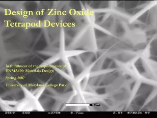
Design of Zinc Oxide Tetrapod Devices. In fulfillment of the requirements of ENMA490: Materials Design Spring 2007 University of Maryland College Park.

E N D
Design of Zinc Oxide Tetrapod Devices In fulfillment of the requirements of ENMA490: Materials Design Spring 2007 University of Maryland College Park
From Left: Michael Figueroa, Abiodun Osho, ,Yilin Liu, Arthur M. Grace, Matthew Castille, Margaret Bennett, Patrick Stahl, Aron Cepler, Paul Pineau Not Pictured: Brian Smith Special Thanks to Professor Gary Rubloff and Parag Banerjee for their guidance and technical support. Thanks also to Susan Beatty, Dr. Tim Zhang, Laurent Henn-Lecordier Tom Loughran, Cytimmune, and Northrop Grumman. Work completed at Materials Teaching Lab, FabLab, LAMP Lab, and NISP Lab.
Outline • Motivation • Logistics • Timeline • Fabrication of Nanostructures • Different Device Concepts • Integration and Testing of Devices • Lessons Learned • Future Work • Summary
Motivation • The unique characteristics of ZnO nanomaterials (wide band gap, piezoelectric effect) lends them great potential for UV and pressure sensing applications. • Nanomaterials require precise structural and electrical characterization which are complicated by their size. • In order to use ZnO nanostructures successfully in macro-scale devices, we must develop effective means to integrate nanostructures into a working device.
The ENMA 490 class was divided into 5 different groups: Research, Management/Writing, Synthesis, Device Design, Integration/Application Research: Use scholarly articles to understand properties of ZnO nanoparticles Management/Writing: Guide all groups in the right direction; major writer of report and presentation Synthesis: Making nanoparticles Device design/fabrication: Work out physical problems with device (i.e. attaching nanoparticles to substrate) Integration/Application: Testing of devices produced Group membership was not static; many members moved around to different groups as needed Logistics
2/12 First Nano structures 2/26 Made Electrode mask 3/12 Finish Mid term presentation SEM of Gold Nano particles 3/12 Take SEM of First of first Finish Mid term presentation 4/2 Made 6 PDMS Test First Device Testing of 6 PDMS device 4/9 Made Kapton tape device 4/16 Made PDMS covered device 4/16 Test PDMS devices 4/23 Made quantitative testing device, PVA, Kapton, PVA devices Milestones Spring Break
Synthesis of the Nanostructures Used Vapor Phase Transport Method Furnace Valves O2 Ar • Argon and Oxygen gas flow • Bubbles per minute controlled the rate • Inside the tube, solid reagents were placed in the boat. • In some runs, Si wafers with gold catalyst were placed downstream from the boat. Glass Tube Gas Flow Alumina Boat
Processing Condition A: No Wafer • Solid Reagents: Zn metal powder • Gas Flow: Ar- 30 bubbles/min O2- 10 bubbles/min • 850 Celsius and held for 90 minutes. • Initially only Ar gas, then turn on O2 gas when system reached 410 degrees. • Results show a fluffy white product throughout much of the tube. • See Zinc Oxide Tetrapod Structures (ZOT) from ESEM images: Scale Bar: 20μm Scale Bar: 5μm
Si Wafer, Scale Bar: 1μm GaN Wafer, Scale Bar: 1μm Processing Condition B: Colloidal Gold • Reasoning: Instead of Zn and O2 reacting in air (or on the glass tube/ceramic boat) to form tetrapods, a catalyst-induced nucleation may cause linear rods to grow. • Cytimmune: 26 nm in 133 μg/ml H20 • Applied colloid to Si and GaN wafers. • Placed Zn powder in boat and wafers downstream from boat. Same gas flow and temperature conditions as Experiment A
Processing Condition C: ZnO and Graphite with Colloidal Gold Scale Bar: 2 μm • ZnO and graphite source material instead of Zn powder. • Use 1:1 ratio of ZnO and graphite powder. Only use Argon for gas flow. Heat to 900 degrees and dwell for 90 minutes. • Mechanism: ZnO powder is reduced by graphite to form Zn and CO vapor at high T (carbothermal reduction). • Zn vapor flows downstream to form alloy with Au colloid. • Vapor-Liquid-Solid growth: ZnO nanowires form, possibly from Zn and CO reaction. Tube setup from left: GaN, Si, Boat with mixed 1:1 ratio of ZnO and graphite
Processing Condition D: Gold Coated Wafers • Motivation: a uniform 10 nm gold-coated Si wafer will induce better nucleation sites for nanorod growth than colloidal gold • Used ZnO and C powder with Ar and O2 gas • Heated to 900 Celsius • See rod-like structures, forming more material than with gold colloid processing conditions. • Conclusions from nanostructure synthesis: • Processing Condition A (without wafer) produced high yield of ZnO tetrapods (ZOTs). • Methods employing wafers with gold colloid or coating were able to grow nanorods, but not in high enough yield to collect and use in devices. • All devices used ZOTs fabricated from processing condition A. Scale Bar: 10μm
In Figure A, the unaligned nanostructures are placed between two electrodes. In Figure B, a pattern is used to induce alignment in rod-like nanomaterial. In both figures, the light blue area indicates nanomaterial, yellow block show the polymer matrix, and dark blue shapes represent the electrodes One concept involved use of a patterned catalyst (red) to grow vertically aligned nanorods. Horizontal and Vertical Device Concepts Horizontal Device Top View Vertical Device Cross Section Figure A Figure B
Multiple electrode variations were fabricated Common features include a protective layer of photoresist to cover the electrodes and two holes in the layer to provide contact points One version had trenches between the electrodes. If a polymer-dispersed method was used, the trenches were intended to keep the liquid dispersed nanomaterial in place. Another version has one open field between the electrodes. Two masks were used to create each electrode design Horizontal Device Processing Photoresist Active Area Trenches Contact Holes Au Electrode
Integrating Nanomaterial into Device • Langmuir-Blodgett and integration via PDMS fluidic flows were investigated. These techniques were considered too complex for our time frame. • Polymer matrix dispersions chosen • Various polymers were researched and utilized in experiments Kapton PDMS PVA Glue Jung, et al. Nano Letters, Vol.,6, No. 3 413-418. 2006 www2.dupont.com/Kapton/en_US/assets/downloads/pdf/summaryofprop.pdf
Our First Device Scale Bar: 20μm • Two silver paint contacts on a microscope slide ~½ inch apart. • A pile of ZOT was placed in between (see A). • More silver paint was applied at the contact regions (see B). An ESEM image of the Ag contact / ZOT interface. Scale Bar: 5μm A B A higher magnification of the Ag / ZOT interface. The arrow indicates a ZOT arm clearly embedded in the contact metal..
Proof of Concept: Initial Device Testing • The device was tested on the probe station in the Kim Building teaching lab. • Force was applied by hand with a glass rod laying across the nanoparticles. • Light was applied with a lamp at the work station • From both tests we saw electrical response and decided to investigate pressure applications of ZnO nanostructures
Considerations: Pressure Device • Before we integrated the ZOT into our microdevice we needed to test several approaches by making macrodevices using: • Kapton Tape • PDMS • Poly Vinyl Acetate Glue • The qualitative results obtained from these macrodevices would allow us to select the best method of integration into our microdevices. • Considerations we wanted to address in our macrodevice were: • ZOT connectivity in the given integration method • Noticeable electrical response to stimuli • Structural Stability of the device • Ease of integration into microdevice
Zinc Oxide Tetrapods (ZOT) in PDMS For our pressure sensing device, we investigated two devices that used PDMS. The first device contained a mixture of PDMS and the ZOT powder The IV curve of 29 wt. % ZOT shows a lack of repeatability. It was determined through ESEM images that there was little connectivity between the dispersed ZOT at this wt.% High wt.% designs were too mechanically unstable to test. 29 wt. % ZOT suspended in PDMS
PDMS Cover Design • Pile of ZOT (similar to device one) covered with PDMS and degassed. • When we reversed the device, unique characteristics were observed as shown in the curve • From this device we concluded that: • When we reversed the polarities, the results were not reproducible • There was a noticeable response to pressure • These unique characteristics were too complex for our timeframe ZOT powder covered with PDMS
Kapton Tape over Nanorods For our second device we decided to essentially bundle the nanostructures with Kapton tape From our tests we concluded that there is an electrical response with the application of pressure within the device but integration of the Kapton tape into a microdevice would be very difficult
PVA Adhesive and ZOT • Neutral pH adhesive (polyvinyl acetate based; PVA) was diluted with water • Integration Methods: • dripping diluted glue onto the powder in place • mixing a slurry of glue, water and ZOT and depositing this on the substrate. • From this we concluded: • The nanorods had an electrical response with the application of pressure • There was relative ease in making the device • That we had created a structurally stable structure
Device Selection • From the qualitative data we obtained from the macrodevices, we decided to further our venture into a microdevice using PVA glue as an integration staple because: • We felt it would be easiest to integrate • There was discernable electrical response (which allowed us to assume there was good conductivity) • The structure of the device was stable
Quantifying Pressure Sensing Apparatus created to apply quantifiable pressure on device. Rubber tip diameter is 3mm In order to adequately access whether the conductance/resistance is changing with pressure we made a special platform that allowed us to apply quantifiable pressure on top of a device. What we expect is that the conductance should decrease with the application of pressure
Pressure Testing: Glue Dispersed Powder on the Au Patterned Electrodes Increasing Pressure Increasing Pressure As the applied pressure increases, a noticeable decrease in the slope is shown.
Pressure Testing: Glue Dispersed Powder on the Au Patterned Electrodes Increasing Pressure Increasing Resistance Resistance varies with pressure between 1.5 and 3.5 V in both positive and negative regions.
Lessons Learned • Working in a group of 10 is challenging: • Organization • Communication • Scheduling • Even though BlackBoard is a good tool, individual lab notebooks would have been useful • Competition for resources/equipment is fierce • Planning and executing a multi-phased project requires technical foresight.
Future Work • Better apparatus for applying quantifiable pressure • Worth quantitatively investigating capacitance as a function of voltage • Comparing electrical and piezoelectric response of nanorods versus tetrapods • Modeling pressure versus resistance from data we obtain is necessary in order to: • Make a predictable device • Understand the nanomechanics of ZOT PVA composite
Summary • Synthesized nanorods and tetrapods using vapor transport growth • Used lithography to create two horizontal electrode designs on silicon wafers • Integrated tetrapods into macroscale devices with: • Kapton Tape • PDMS • PVA Glue • Observed I-V response to pressure and light stimuli in devices • Quantified pressure effects on resistance on a wafer device