
SiGe
E N D
Presentation Transcript
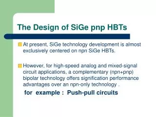
SiGe A complementary BiCMOS technology with High Speed npn and pnp SiGe:C HBTs
Abstract • Demonstrate SiGe:C pnp HBTs in a complementary bipolar CMOS flow with ft/fmax values of 80GHz/120GHz at BVceo=2.6v,ring oscillator delay 8.9ps • Npn-noly BiCMOS ft/fmax has the value of 180GHz/185GHz , a ring oscillator delay 4.6ps • Pnp-only BiCMOS produces peak ft/fmax values for pnp devices of 115GHz/115GHz
Introduction • The availability of both npn-and pnp-type bipolar transistors with matched performance can significantly reduce the power consumption of high speed bipolar circuits • Optimization of heterojunction pnp transistors for operation at high speed has to consider not only the effect of poorer transport parameters of holes compared to electrons • Careful profile design is required for pnp SiGe HBTs to minimize the deleterious impact of valence band barriers before the onset of the Kirk effect • Si/Si(1-y)C(y) layers offer a band lineup that is more suited for pnp HBTs than the Si/Si(1-x)Ge(x) system • Carbon fraction needed for a sufficient gain enhancement would lead to strain relaxation and precipitation during a typical final RTA step in a BiCMOS process and constraints of the process flexibility
Si/SiGe pnp heterojunction bipolar transistors • (a) what is the problem to make a pnp transitors using Si/SiGe heterojunction? • (b) how to solve it using the Si/SiGe heterojunction • (c)is Si/SiC heterjunction better for pnp HBT?why?
(a) Si/SiGe pnp. P N P Is fixed. Ef C E B If some SiGe diffuse to Emitter. Si SiGe Current small !! Plastic barrier
We do not want • Not only the effect of poorer transport parameters of hole compared to electrons.due to the band lineup in the Si/SiGe system,careful profile design is required for pnp SiGe HBT.to minimize the deleterious impact of valence band barriers before the onset of the kirk effect.
(b) • If control SiGe in base region Is better !!
(c)Si/SiC heterjunction is better for pnp HBT Si/SiC layers offer a band lineup that is more suited for pnp HBTs than the Si/SiGe System. However, a carbon fraction needed for a sufficient gain enhancement would Lead to strain relaxation and precipitation during a typical final RTA step.
Introduction(2) • A complementary bipolar (CBi)CMOS process with an isolated SiGe:C pnp-HBT whose high speed performance significantly exceeds all previously reported data. • The performance gain of the pnp-HBTs is mainly due to a highly tuned vertical doping profile taking full advantage of the reduced P diffusion in the C-doped base combined with the special collector construction of previously reported 200GHz npn transistors • The construction allows one to integrate an isolated pnp into a CMOS process easily ,while simultaneously minimizing collector resistance and capacitance.
A key feature of both the npn and the pnp HBT process is the formation of the whole HBT Structure in one active area without shallow trench isolation between the active emitter and The collector contact region.This allows one to achievelow-capacitance isolation from The substrate ,and low collector resistance for both types of transistors.
Device fabrication and design Schematic flow of the complementary BiCMOS process
Device parameter The formation of the whole HBT structure in one active area without shallow trench Isolation between the active emitter and the collector contact region. This allows one to achieve low-capacitance isolation from the substrate and low Collector resistance for both types of transistors.
Device results Ico Ibo Ic Ib These devices have a current gain of 160 and 180 at V(be)=0.7v,andBV(CEO) values of 2.0v and 2.6v for npn and pnp HBTs respectively
Peak values of 110-120 ghZ for both Pnp preparations exceed by a factor Of 2 all previously reported values for Pnp bipolar devices. The lower peak ft of the CBiCMOS pnp Compared to the pnp-only flow is due To reduced collector doping.(3c-32) A lower base resistance and a higher F(max) are obtained in the CBiMOS Process,because the base link region Is enhanced by the npn emitter poly. CBiCMOS BiCMOS CBiCMOS
CBiCMOS A minimum gate delay of 8.9ps was measured for npn CML ring oscillator of the CBiCMOS Process,representing the best reported values for pnp based ROs so far. The npn HBTs of the CBiCMOS flow reach ft/fmax values of 180GHz/185GHz and a gate Delay of 4.6ps. This performance is almost as high as that of the reference BiCMOS ,despite the changed Emitter construction and the additional thermal budget within the CBiCMOS process.
Current gain =Ic/Ib Figs.7 and8 show the current gain and ft as a function of collector current at different collector biases for the pnp HBTs.
The weak sensitivity of current gain and peak ft to the collector bias and the high Early Voltage at low V(ce) indicate that valence band barrier effects are largely suppressed before onset of the Kirk effect. This was achieved by a careful profile design at the base-collector junction.
Conclusions • This paper have demonstrated SiGe:C pnp HBTs with ft/f(max) values exceeding 100GHz.High-speed pnp and npn devices have been integrated into a complementary bipolar CMOS process. This process is a promising route to applications simultaneously requiring low voltage,low power, and high speed .
Reference • 2003 IEDM
SiGe • SiGe:C BiCMOS Technology with 3.6ps Gate Delay
Abstract • A high-speed SiGe:C HBT technology is presented that combines a new extrinsic base construction with a low resistance collector design to simultaneously minimizebase and collector resistances and base collector capacitance • A ring oscillator delay of 3.6ps per stage was achieved • The HBTs demonstrate an f(t) of 190GHz,an f(max) of 243 GHz and a BV(CEO) OF 1.9V at an drawn emitter size of 0.175*0.84 um^(2)
Introduction • SiGe BiCMOS technology is a strong contender for enabling communication speeds inexcess of 100 Gb/s and wireless systems in the 100GHz range. • This has led to new device structures that reduce base and collector resistance and to a vertical and lateral device scaling resulting in f(t) and f(max) values above 200GHz • Here,we report on a high-speed SiGe:C HBT technology that combines a new extrinsic base construction with a low resistance collector design to simultaneously minimize base resistance, collector resistance and base-collector capacitance. • (i)Gate delays of3.6ps per stage are achieved for CML ring oscillators at a differential voltage swing of 300mV (ii)The HBTs demonstrate of f(t) of 190 GHz an f(max) of 243 GHz and a BV(CEO) of 1.9v at an emitter size of 0.175*0.84um^(2).(iii)The high speed HBT module has been integrated in a 0.25um CMOS platform, without altering any CMOS device characteristics.
Device fabrication Process sequence for fabrication of the HBT module. The key new device feature is the formation of an elevated extrinsic base region by Selective epitaxial growth of B-doped Si after structuring the poly Si emitter.
The elevated extrinsic base is self-aligned to the active emitter to minimize base resistance
The HBT stack and the collector contact are formed in one active area and no deep Trenches are needed for device isolation to minimize R(C) AND C(BC) The HBT without the elevated extrinsic base ,in this process the extrinsic base is formed by ion implantation after emitter structuring.
Device results:A. DC characteristics Current gain=300 at V(BE)=0.7V Gummel characteristics of HBTs with elevated extrinsic base
The open-base E-C breakdown voltage BV(CEO)=1.9V Common emitter output characteristics at constant base current
Device results:B. RF characteristics 225 Due to reduced R(B) and C(BC) for the devices with elevated extrinsic base. 186 For reference HBTs with implanted extrinsic base(lines) With elevated extrinsic base(lines with circles) Both transistors have similar f(T) curves due to almost Identical doping profiles in the active transistor region. Ft(Ic)Fmax(Ic) curves of transistors with the elevated extrinsic base are compared with Reference transistors with implanted extrinsic base
A further reduction of the base resistance was achieved by shrinking the drawn emitter Width to 0.175um.As a result, f(max) increased to 243 GHz for the device with Shrunk Emitter width.
Mason’s unilateral gain With elevated extrinsic base Deembedded small signal current gain h(21) and unilateral gain U vs frequency.f(t) and f(max) were extrapolated at 30 GHz with -20dB decay per frequency decade. Two Transistors in parallel were measured.
Implanted extrinsic base with elevated extrinsic base and different Emitter dimensions This delay is shorter than all previously reported Values for SiGe technologies CML ring oscillator gate delay vs current per gate for oscillators with 53 stages and a Differential voltage swing of 300mv.devices with elevated extrinsic base and different Emitter dimensions( lines with circles) are compared with reference devices with Implanted extrinsic base (solid line)
The comparison of the gate delays for the two different base contact technologies illustrates the impact of individual device parameters. Although both processes gave almost identical transit frequencies f(t) for HBTs with 0.21um emitter width, the gate delay decreased from 4.3ps for the devices with implanted extrinsic base to 3.9ps for devices with elevated extrinsic base. This gain in circuit speed is mainly due to the reduction of R(B) and C(BC),the further reduction of R(B) and C(BC) due to shrinking the drawn emitter width to 0.175um led to the reduction of the gate delay to3.6ps
Conclusions • Ring oscillator gate delays of 3.6ps per stage have been demonstrated in a SiGe:C BiCMOS technology featuring HBTs with ft/f(max) of 190GHz/243GHz.The achieved reduction of the stage delay was due to a new device construction with reduced base resistance and base-collector capacitance .This performance further establishes the potential of SiGe:C technology for communication speeds exceeding 100Gb/s and 100GHz.
Reference • IEDM 2003