Magnetic field H
900 likes | 1.32k Views
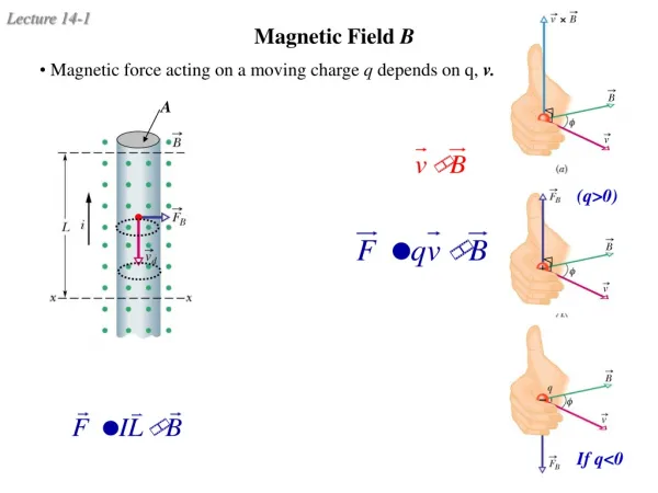
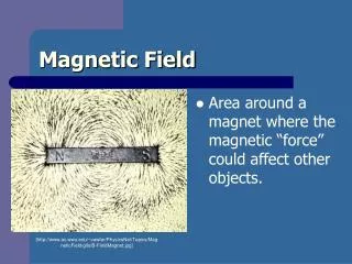
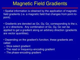
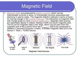
Electric field E. Magnetic field H. Direction of propagation. The light wave is comprised of an electric field and a magnetic field . The magnetic field, H is always perpendicular to the electric field. Phase. these two waves are in phase. 1/2 l difference = 180 deg. Phase.

Magnetic field H
E N D
Presentation Transcript
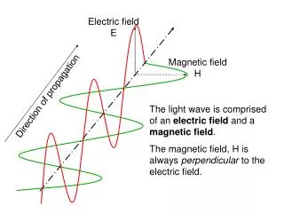
Electric field E Magnetic field H Direction of propagation The light wave is comprised of an electric field and a magnetic field. The magnetic field, H is always perpendicular to the electric field.
Phase these two waves are in phase
1/2 l difference = 180 deg Phase these two waves are out of phase
A1+A2 Superposition A1 A2 Add amplitudes for waves that are in phase
A1-A2 Superposition A1 A2 Subtract amplitudes for waves that are out of phase by 180 deg
A1-A2=0 Superposition Total destructive interference A1 A2 A1 = A2but thewaves are out of phase by 180 deg.
Mutual Coherence Two waves are said to be mutually coherent when the phase difference between the two waves does not change over time. (i.e. the crest of the first wave is always a fixed distance from the crest of the second wave) When the phase difference between two waves varies over time, the waves are said to be mutually incoherent.
Mutual Coherence • Coherent sources are generally derived from the same source. That way, both waves have the same wavelength and the same random fluctuations in phase*. *The wavetrain from any source (including a laser) is not constant but undergoes random changes in phase
Coherence Length The distance over which a wave can interfere with itself * * or …. The average length of a wavetrain • coherence length for.. • laser: many meters • low-coherent laser: 10 nm • sun: 2 mm
Examples 1.What is the intensity of two mutually coherent waves, one with amplitude 5 and another with amplitude 13 and a phase difference between the two of a) 90 degrees? b) 180 degrees? 2. What is the intensity of two mutually incoherent waves, one with amplitude 5 and another with amplitude 13?
Consider this example… If two mutually coherent waves of amplitude 5 and 10 respectively have a combined intensity of 135, what is the phase difference between them?
peak valley valley peak peak valley valley peak peak valley valley Young’s Double Slit single light source
peak valley valley peak peak valley valley peak peak valley valley Young’s Double Slit I screen single light source
Young’s Double Slit Calculation Dd Slit separation = a q q y s
Young’s Double Slit Calculation Substitute in the expression for phase difference
Young’s double slit • Maxima occur whenever y – position on screen m – counter l – wavelength s – distance from aperture to screen a – slit separation
Young’s double slit interference pattern for monochromatic light y m= 3 m= 2 m= 1 m=0 m=-1 m=-2 m=-3
Example • Given an aperture with a 0.1 mm slit spacing, a wavelength of 500 nm, and a screen held at a distance of 2 m. What is the separation between maxima? • What is the separation for 400 nm light?
Lloyd’s mirror interference S mirror S’
Fresnel’s double prism S’1 interference S S’2 two thin prisms
Michelson Interferometer to Characterize Actuator Deflection of a MEMS DM.
Applications of Interference
Retinal Interference PatternsPotential Acuity Meter cataract The laser beams bypass the cataract and generate scatter-free, high resolution interference fringes on the retina to test retinal function prior to cataract removal.
Thin Film Interference What happens to a reflected wave when n2 > n1? n2 n1 incident wave reflected wave Reflected wave isshifted in phase by180º (1/2 cycle)
Thin Film Interference What happens to a reflected wave when n2 < n1? n2 n1 incident wave reflected wave n2 < n1 Reflected wave continues with no change in phase
no ARC with ARC Reflectance of an AR Coating 4 3 reflectance (%) 2 1 400 550 700 l
Why do ARCs Appear Purplish? • green reflection is eliminated • some reddish and bluish reflectance remains (see graph) • mixture of red and blue has purplish hue • reflected color will change with angle since effective thickness of coating changes
Thin Film Problem • What is the reflectance of a glass (n=1.5) surface with a MgFl2 coating (n=1.38) optimized for 550 nm light for • 550 nm light? • 400 nm light?
Step 1 • What is the thickness of the coating?
Step 2 • What is the amplitude of reflectance at the surfaces?
Step 3 • For 550 nm light….
Step 4 • For 400 nm light, what is the phase difference?
Step 5 • For 400 nm light
Summary • If the phase changes are common to both surfaces (eg ARC), then
Summary • If the phase changes are not common to both surfaces (eg soap bubble, or oil), then
Fringes of Equal Thickness Problem • Two flat microscope slides, 10 cm long, are touching at one end and are separated by three microns on the other. How many dark interference bands will appear on the slide if you look at the reflection for 450 nm light?
Diffraction “Any deviation of light rays from a rectilinear path which cannot be interpreted as reflection or refraction” Sommerfeld, ~ 1894
Huygen’s Principle Huygens' principle applied to both plane and spherical waves. Each point on the wave front AA¢ can be thought of as a radiator of a spherical wave that expands out with velocity c, traveling a distance ct after time t. A secondary wave front BB¢ is formed from the addition of all the wave amplitudes from the wave front AA¢.
Fraunhofer Diffraction • Also called far-field diffraction • Occurs when the screen is held far from the aperture. • Occurs at the focal point of a lens
Diffraction and Interference • diffraction causes light to bend perpendicular to the direction of the diffracting edge • interference due to the size of the aperture causes the diffracted light to have peaks and valleys