ELE2MIC Lecture 21
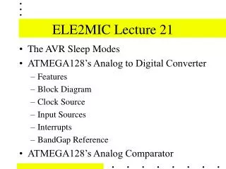
ELE2MIC Lecture 21. The AVR Sleep Modes ATMEGA128’s Analog to Digital Converter Features Block Diagram Clock Source Input Sources Interrupts BandGap Reference ATMEGA128’s Analog Comparator. Analog to Digital Converter (ADC) Features. 10-bit Resolution 0.5 LSB Integral Non-linearity

ELE2MIC Lecture 21
E N D
Presentation Transcript
ELE2MIC Lecture 21 • The AVR Sleep Modes • ATMEGA128’s Analog to Digital Converter • Features • Block Diagram • Clock Source • Input Sources • Interrupts • BandGap Reference • ATMEGA128’s Analog Comparator
Analog to Digital Converter (ADC) Features • 10-bit Resolution • 0.5 LSB Integral Non-linearity • ±2 LSB Absolute Accuracy • 13 - 260 µs Conversion Time • Up to 15 kSPS at Maximum Resolution • 8 Multiplexed Single Ended Input Channels • 7 Differential Input Channels
ADC Features Continued • 2 Differential Input Channels with Optional Gain of 10x and 200x • Optional Left Adjustment for ADC Result Readout • 0 - VCC ADC Input Voltage Range • Selectable 2.56 V ADC Reference Voltage • Free Running or Single Conversion Mode • Interrupt on ADC Conversion Complete • Sleep Mode Noise Canceler
ADC Operation The ADC converts an analog input voltage to a 10-bit digital value through successive approximation. The minimum value represents GND and the maximum value represents the voltage on the AREF pin minus 1 LSB. Optionally, AVCC or an internal 2.56V reference voltage may be connected to the AREF pin by writing to the REFSn bits in the ADMUX Register. The internal voltage reference may be decoupled by an external capacitor at the AREF pin to improve noise immunity.
ADC Control and Status Register Bit 6 – ADSC: ADC Start Conversion In Single Conversion mode, write this bit to one to start each conversion. In Free Running mode, write this bit to one to start the first conversion. The first conversion after ADSC has been written after the ADC has been enabled, or if ADSC is written at the same time as the ADC is enabled, will take 25 ADC clock cycles, instead of the normal 13. This first conversion performs initialisation of the ADC. When the conversion is complete, ADSC returns to zero. Writing zero to this bit has no effect.
ADC Enable - ADEN Bit 7 – ADEN: ADC Enable - The ADC is enabled by setting (writing this bit to one) the ADC Enable bit, ADEN in ADCSRA. By writing ADEN to zero, the ADC is turned off. Turning the ADC off while a conversion is in progress, will terminate this conversion. Voltage reference and input channel selections will not go into effect until ADEN is set. The ADC does not consume power when ADEN is cleared, so it is recommended to switch off the ADC before entering power saving sleep modes.
ADC Free Running - ADFR Bit 5 – ADFR: ADC Free Running Select When this bit is written to one, the ADC operates in Free Running mode. In this mode, the ADC samples and updates the data registers continuously. Writing zero to this bit will terminate Free Running mode.
ADC Interrupt Enable - ADIE Bit 3 – ADIE: ADC Interrupt Enable When this bit is written to one and the I-bit in SREG is set, the ADC Conversion Complete Interrupt is activated.
ADC Interrupt Flag - ADIF Bit 4 – ADIF: ADC Interrupt Flag This bit is set when an ADC conversion completes and the data registers are updated. The ADC Conversion Complete Interrupt is executed if the ADIE bit and the I-bit in SREG are set. ADIF is cleared by hardware when executing the corresponding interrupt handling vector. Alternatively, ADIF is cleared by writing a logical one to the flag. Beware that if doing a read-modify-write on ADCSRA, a pending interrupt can be disabled.This also applies if the SBI and CBI instructions are used.
ADC PreScaler Select Bits 2:0 – ADPS2:0: ADC Prescaler Select Bits These bits determine the division factor between the XTAL frequency and the input clock to the ADC.
ADC Result - ADLAR Results with ADLAR=0 (Right Adjusted Result) Results with ADLAR=1 (Left Adjusted Result)
ADC Result - ADCH/ADCL The ADC generates a 10-bit result which is presented in the ADC Data Registers, ADCH and ADCL. By default, the result is presented right adjusted, but can optionally be presented left adjusted by setting the ADLAR bit in ADMUX. If the result is left adjusted and no more than 8-bit precision is required, it is sufficient to read ADCH.
ADC Result - ADCH/ADCL Otherwise, ADCL must be read first, then ADCH, to ensure that the content of the data registers belongs to the same conversion. Once ADCL is read, ADC access to data registers is blocked. This means that if ADCL has been read, and a conversion completes before ADCH is read, neither register is updated and the result from the conversion is lost. When ADCH is read, ADC access to the ADCH and ADCL Registers is re-enabled.
ADC Interrupt - ADIE, ADIF The ADC has its own interrupt which can be triggered when a conversion completes. When ADC access to the data registers is prohibited between reading of ADCH and ADCL, the interrupt will trigger even if the result is lost.
ADC ADMUX REFS1..REFS0 - Select the ADC Reference Voltage ADLAR - Left Adjust Result MUX4..0 - Analog Input Multiplexor select bits. MUX4..MUX0 select the ADC input source & type
ADC ADMUX - REFS1..0 REFS1..REFS0 - Select the ADC Reference Voltage
ADC ADMUX - MUX4..0 MUX4..0 - Select the ADC input source, gain & type