Download
1 / 36
360 likes | 451 Views
Explore various stress measurement techniques in scientific drilling, including breakout analysis, ASR method, and modeling to obtain a complete three-dimensional stress tensor. Learn how to determine stress orientations and magnitudes using borehole methods and imaging of breakouts. Follow IODP experiments for practical insights.

E N D
Current stress measurement in scientific drillingWeiren LIN(Kochi / JAMSTEC)Special thanks to TCDP and NanTroSEIZE colleaguesTCDP: C-Y Wang; K-F Ma; J-H Hung; S-R Song; H. Ito; B. Haimson, H-Y Wu, etcNanTro: T. Byrne; C Chang; A Tsutsumi; A Sakaguchi; M Kinoshita; H Tobin, etc
Basic standpoints: how obtain a complete stress tensor= three dimensional stresses • There is no foolproof method by which the magnitudes and orientations of three-dimensional in situ stresses can be reliably measured at great depth. • It is desirable to combine borehole methods, core-based methods, modeling to obtain a complete three-dimensional picture of in situ stress.
Several stress measurement methods • Breakout (Stress induced compressive failure) • Drilling induced tensile fracture • Extended Leak Off Test (XLOT) / Hydraulic fracturing • An example of core based method: Anelastic Strain Recovery (ASR) • Modeling: Anderson’s fault law
Obtaining a complete stress tensor -- Basic assumption: vertical direction is one of three principal orientations -- • Principal stress orientation • Vertical stress magnitude • Minimum horizontal stress magnitude • Maximum horizontal stress magnitude
Is vertical direction one of three principal orientations? Ground If it is just after fault rupturing, shear stress on the fault plane may be almost zero. Then, orientation along the fault is one of orientations of principal stresses. Fault Answer: No! Especially, near active fault! But this assumption is realistic for today measurement technologys.
Obtaining a complete stress tensor -- Basic assumption: vertical direction is one of three principal orientations -- • Stress orientation • Vertical stress magnitude • Minimum horizontal stress magnitude • Maximum horizontal stress magnitude
Obtaining a complete stress tensor -- Basic assumption: vertical direction is one of three principal orientations -- • Principal stress orientation • Vertical stress magnitude • Minimum horizontal stress magnitude • Maximum horizontal stress magnitude • Breakouts • ASR measurements
What is breakouts? SHmax • Far field stress in horizontal plane • Before drilling • Stress state • at borehole wall • After drilling sq sr Shmin Mud pressure If sq max>compressive strength, compressive failure occurs Stress induced compressive failure=Breakout
Dose breakout occurs or do not? • Actually, a complex failure criteria • Simply manner: sq>compressive strength • sqmax<strength →no breakout • sqmin<strength and sqmax>strength →easily to determine stress orientation • sqmax>sqmin>strength →unstable borehole, difficultly to determine stress orientation
How obtain imaging of breakouts? Image logs: FMI, UBI, (calliper) … Application of breakouts 1. Determine orientations of Shmin and SHmax 2. Estimate magnitude of SHmax
Borehole Breakout Images (LWD)_NanTriSEIZE IODP Exp. 314 C0001 C0002 C0004 IODP Exp 314 Preliminary Report
Stress orientation (depth <1.5 km) Direction of horizontal compression or extension at drilled sites. Yellow arrow shows the direction of the movement of Philippine Sea Plate relative to Honshu arc. 掘削サイトにおける水平最大圧縮場および伸張場の方向。C0001・C0004では北西南東方向に圧縮、C0002では伸張であることが分かった。黄色:フィリピン海プレートが本州に沈み込む方向。 SHmax orientation IODP Exp 314 Preliminary Report
NanTroSEIZE Stage 1A_ASR test • 1.Exp 315, C0002B, 884 mbsf, Mudstone2.Exp 315, C0002B, 912 mbsf, Mudstone 3.Exp 316, C0006F, 468 mbsf, Mudstone ASR 1, 2 ASR 3 IODP Exp 314 Preliminary Report
Strain/ Stress Loading Unloading Time Anelastic strain Creep Concept of ASR method Stepwise loading or unloading s ea∝s • Visco-elastic mmaterial • Homogeneous and isotropic • Three-dimensional • Measure as rapid as possible • Cheaper
Basic equations of ASR method • Rock: homogeneous, isotropic and viscoelastic material • ea(t)=(1/3)[(3l2-1)sx+(3m2-1)sy+(3n2-1)sz+6lmtxy+6mntyz+6nltzx]Jas(t) +(sm-p0)Jav(t) (in the case of no temperature change) where, sx, sy, sz, txy, tyz, tzx,:stress tensor p0: pore pressure Jas, Jav: anelastic strain compliance l,m,n: direction cosine • Measure anelastic strain in six independent directions • Principal stress orientation = Principal strain orientation
ASRmeasurement system(apparatus) ・On site laboratory ・To keep temperature constant ・Measure anelastic strain several days - weeks
ASR Sample: C0002B, 912 mbsf 55mm 定方位:超伝導磁力計による残留磁化強度
図-1 南海トラフ掘削Exp.315コア試料の非弾性ひずみの経時変化の一例.曲線のラベル(X, Yなど)はひずみの測定方向を示している. Anelastic strain recovery curves(C0002B, 912mbsf, 7.5 days)
Horizontal orientation by ASR(C0002B, 912mbsf) SHmax orientation Stress orientations by breakout and ASR are consistent with each other. Normal fault stress regime. IODP Exp 314 Preliminary Report
300-400年に一回,計12kmの食い違い変位量 Hole-A: 500~2000m(2004) Hole-B:950~1350m(2005)
Tectonic stress direction SHmax orientationsin TCDP hole-B TCDP Hole-B, Many breakouts and a few DITF Lin et al., 2007_GRL 1st FZ Rotation of principal stress was induced by fault rupturing
Obtaining a complete stress tensor • Basic assumption: vertical direction is one of principal orientation • Stress orientation • Vertical stress magnitude • Minimum horizontal stress magnitude • Maximum horizontal stress magnitude
z 0 ( ) S z = ò r g dz v 0 0 Vertical stress magnitude • Assumption: vertical stress=overburden pressure
Obtaining a complete stress tensor -- Basic assumption: vertical direction is one of three principal orientations -- • Stress orientation • Vertical stress magnitude • Minimum horizontal stress magnitude • Maximum horizontal stress magnitude Extended Leak Off Test Hydraulic fracturing
XLOT_ a typical system _ to measure the minimum stress Obtain minimum stress from the pressure curve If the measured minimum stress<<vertical stress → it is minimum horizontal stress. If the measured minimum stress is almost equal to vertical stress → need other method to determine the minimum horizontal stress, e.g. core methods Hydraulic Fractures Propagate Perpendicular to the Min Principal Stress
XLOT: a typical pumping pressure chart (after White et al., 2002)
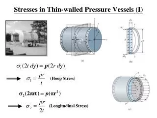
Obtaining a complete stress tensor -- Basic assumption: vertical direction is one of three principal orientations -- • Stress orientation • Vertical stress magnitude • Minimum horizontal stress magnitude • Maximum horizontal stress magnitude Breakout width (span)
Compressive failure criteria • Best test condition • Unjacketed • Criteria: True triaxial compression test • (s2=sz,s3=sr) • (Haimson et al, 2002_JGR) sz sq • Simple test condition • Unjacketed → s3eff = s3-Pp = 0 • Neglect “intermediate stress s2 effect” • Criteria: Uniaxial compression test • (s2=s3=0) • (Barton et al, 1988_JGR) sr Haimson et al, 2008 (submitted)
Equation to estimating SHmax(based on uniaxial compressive criteria) • Uniaxial compressive strength (UCS) =Co • Mud pressure=Pp • SHmax = (Co+2Pp)/(1-2cos2q)-Shmin(1+2cos2q)/(1-2cos2q) • Barton et al., 1988_JGR • If Shmin, Co, Pp are known, SHmax can be estimated from 2q. Haimson et al, 2008 (submitted)
2q profile in TCDP hole-B Haimson et al, 2008 (submitted)
Parameters needed to SHmax estimation • Based on uniaxial compressive criteria • sHmax = (Co+2Pp)/(1-2cos2q)-shmin(1+2cos2q)/(1-2cos2q) • Shmin=Depth/62.5; XLOT,Hung et al, 2007_Tectonophysics • Co=38.7MPa(Siltstone), • 30.4MPa(Sandstone with bioturbation); Chen, 2005_NTU thesis • Pp=Depth/100; Assumed as static pore pressure Haimson et al, 2008 (submitted)
Stress magnitude estimation from ASR measurements (TCDP hole-A, near fault zone at 1111m) • For the specimen taken from 1112m • Assumptions:formation density=2.4 g/cm3; • sv=26 MPa, p0= 11 MPa, Jas=2Jav • s1=28 MPa, s2=24 MPa, s3=19 MPa. • Normal fault regime • Two assumptions to estimate magnitude of principal stresses: • the stress in vertical direction is equal to the overburden stress, • the ratio of anelastic strain recovery compliance of shear deformation and the compliance of volumetric deformation is equal to 2 • si=ei(t)/Jas(t)+em(t)/Jav(t)+p0 i=1,2,3 • (no-temperature change condition)
Stress magnitude constraints in the vicinity of the first major fault zone of TCDP Sv Anderson’s fault law (Zoback et al, 2003), static frictional coef.=0.8
Summary: How to determine stress? • Complement data set • A core-based method: ASR • Obtaining 3D orientation • Estimating 3D stress magnitude based on a stress magnitude (LOT) • Small strain, homogeneous, isotopic? • Basic data set • Z is a principal orientation • Azimuth: breakouts Sz s2 Vertical stress: overburden pressure + SHmax s1 s3 Shmin Max horizontal stress: breakout width Min horizontal stress: XLOT, minifrac, HF impossible in RF
How fast and How deep? • <3 or 5years • >1km