Download

1 / 39
480 likes | 1.96k Views
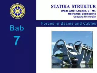
Forces in Beams and Cables. Contents. Introduction Internal Forces in Members Sample Problem 7.1 Various Types of Beam Loading and Support Shear and Bending Moment in a Beam Sample Problem 7.2 Sample Problem 7.3 Relations Among Load, Shear, and Bending Moment. Sample Problem 7.4

E N D
Contents Introduction Internal Forces in Members Sample Problem 7.1 Various Types of Beam Loading and Support Shear and Bending Moment in a Beam Sample Problem 7.2 Sample Problem 7.3 Relations Among Load, Shear, and Bending Moment Sample Problem 7.4 Sample Problem 7.6 Cables With Concentrated Loads Cables With Distributed Loads Parabolic Cable Sample Problem 7.8 Catenary
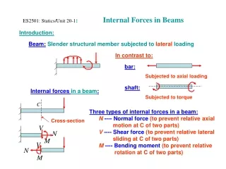
Introduction • Preceding chapters dealt with: • determining external forces acting on a structure and • determining forces which hold together the various members of a structure. • The current chapter is concerned with determining the internalforces (i.e., tension/compression, shear, and bending) which hold together the various parts of a given member. • Focus is on two important types of engineering structures: • Beams - usually long, straight, prismatic members designed to support loads applied at various points along the member. • Cables - flexible members capable of withstanding only tension, designed to support concentrated or distributed loads.
Straight two-force member AB is in equilibrium under application of F and -F. • Multiforce member ABCD is in equil-ibrium under application of cable and member contact forces. • Internal forces equivalent to a force-couple system are necessary for equil-ibrium of free-bodies JD and ABCJ. • An internal force-couple system is required for equilibrium of two-force members which are not straight. Internal Forces in Members • Internal forces equivalent to F and -F are required for equilibrium of free-bodies AC and CB.
Sample Problem 7.1 • SOLUTION: • Compute reactions and forces at connections for each member. • Cut member ACF at J. The internal forces at J are represented by equivalent force-couple system which is determined by considering equilibrium of either part. • Cut member BCD at K. Determine force-couple system equivalent to internal forces at K by applying equilibrium conditions to either part. Determine the internal forces (a) in member ACF at point J and (b) in member BCD at K.
SOLUTION: • Compute reactions and connection forces. Consider entire frame as a free-body: Sample Problem 7.1
Consider member BCD as free-body: Consider member ABE as free-body: From member BCD, Sample Problem 7.1
Cut member ACF at J. The internal forces at J are represented by equivalent force-couple system. Consider free-body AJ: Sample Problem 7.1
Cut member BCD at K. Determine a force-couple system equivalent to internal forces at K . Consider free-body BK: Sample Problem 7.1
Various Types of Beam Loading and Support • Beam - structural member designed to support loads applied at various points along its length. • Beam can be subjected to concentrated loads or distributed loads or combination of both. • Beam design is two-step process: • determine shearing forces and bending moments produced by applied loads • select cross-section best suited to resist shearing forces and bending moments
Various Types of Beam Loading and Support • Beams are classified according to way in which they are supported. • Reactions at beam supports are determinate if they involve only three unknowns. Otherwise, they are statically indeterminate.
Wish to determine bending moment and shearing force at any point in a beam subjected to concentrated and distributed loads. • Determine reactions at supports by treating whole beam as free-body. • Cut beam at C and draw free-body diagrams for AC and CB. By definition, positive sense for internal force-couple systems are as shown. Shear and Bending Moment in a Beam • From equilibrium considerations, determine M and V or M’ and V’.
Variation of shear and bending moment along beam may be plotted. • Determine reactions at supports. • Cut beam at C and consider member AC, • Cut beam at E and consider member EB, • For a beam subjected to concentrated loads, shear is constant between loading points and moment varies linearly. Shear and Bending Moment Diagrams
Sample Problem 7.2 • SOLUTION: • Taking entire beam as a free-body, calculate reactions at B and D. • Find equivalent internal force-couple systems for free-bodies formed by cutting beam on either side of load application points. Draw the shear and bending moment diagrams for the beam and loading shown. • Plot results.
SOLUTION: • Taking entire beam as a free-body, calculate reactions at B and D. • Find equivalent internal force-couple systems at sections on either side of load application points. Similarly, Sample Problem 7.2
Sample Problem 7.2 • Plot results. • Note that shear is of constant value between concentrated loads and bending moment varies linearly.
Sample Problem 7.3 • SOLUTION: • Taking entire beam as free-body, calculate reactions at A and B. • Determine equivalent internal force-couple systems at sections cut within segments AC, CD, and DB. Draw the shear and bending moment diagrams for the beam AB. The distributed load of 40 lb/in. extends over 12 in. of the beam, from A to C, and the 400 lb load is applied at E. • Plot results.
SOLUTION: • Taking entire beam as a free-body, calculate reactions at A and B. Sample Problem 7.3 • Note: The 400 lb load at E may be replaced by a 400 lb force and 1600 lb-in. couple at D.
Evaluate equivalent internal force-couple systems at sections cut within segments AC, CD, and DB. From A to C: From C to D: Sample Problem 7.3
Evaluate equivalent internal force-couple systems at sections cut within segments AC, CD, and DB. From D to B: Sample Problem 7.3
Sample Problem 7.3 • Plot results. From A to C: From C to D: From D to B:
Relations between load and shear: • Relations between shear and bending moment: Relations Among Load, Shear, and Bending Moment
Reactions at supports, • Shear curve, • Moment curve, Relations Among Load, Shear, and Bending Moment
Between concentrated load application points, and shear is constant. • Between concentrated load application points, The change in moment between load application points is equal to area under shear curve between points. Sample Problem 7.4 • SOLUTION: • Taking entire beam as a free-body, determine reactions at supports. • With uniform loading between D and E, the shear variation is linear. Draw the shear and bending-moment diagrams for the beam and loading shown. • With a linear shear variation between D and E, the bending moment diagram is a parabola.
SOLUTION: • Taking entire beam as a free-body, determine reactions at supports. • Between concentrated load application points, and shear is constant. Sample Problem 7.4 • With uniform loading between D and E, the shear variation is linear.
Between concentrated load application points, The change in moment between load application points is equal to area under the shear curve between points. Sample Problem 7.4 • With a linear shear variation between D and E, the bending moment diagram is a parabola.
Sample Problem 7.6 • SOLUTION: • The change in shear between A and B is equal to the negative of area under load curve between points. The linear load curve results in a parabolic shear curve. • With zero load, change in shear between B and C is zero. • The change in moment between A and B is equal to area under shear curve between points. The parabolic shear curve results in a cubic moment curve. Sketch the shear and bending-moment diagrams for the cantilever beam and loading shown. • The change in moment between B and C is equal to area under shear curve between points. The constant shear curve results in a linear moment curve.
Sample Problem 7.6 • SOLUTION: • The change in shear between A and B is equal to negative of area under load curve between points. The linear load curve results in a parabolic shear curve. • With zero load, change in shear between B and C is zero.
Sample Problem 7.6 • The change in moment between A and B is equal to area under shear curve between the points. The parabolic shear curve results in a cubic moment curve. • The change in moment between B and C is equal to area under shear curve between points. The constant shear curve results in a linear moment curve.
Cables With Concentrated Loads • Cables are applied as structural elements in suspension bridges, transmission lines, aerial tramways, guy wires for high towers, etc. • For analysis, assume: • concentrated vertical loads on given vertical lines, • weight of cable is negligible, • cable is flexible, i.e., resistance to bending is small, • portions of cable between successive loads may be treated as two force members • Wish to determine shape of cable, i.e., vertical distance from support A to each load point.
Additional equation is obtained by considering equilibrium of portion of cable AD and assuming that coordinates of point D on the cable are known. The additional equation is • For other points on cable, Cables With Concentrated Loads • Consider entire cable as free-body. Slopes of cable at A and B are not known - two reaction components required at each support. • Four unknowns are involved and three equations of equilibrium are not sufficient to determine the reactions.
Consider free-body for portion of cable extending from lowest point C to given point D. Forces are horizontal force T0 at C and tangential force T at D. • From force triangle: Cables With Distributed Loads • For cable carrying a distributed load: • cable hangs in shape of a curve • internal force is a tension force directed along tangent to curve. • Horizontal component of T is uniform over cable. • Vertical component of T is equal to magnitude of W measured from lowest point. • Tension is minimum at lowest point and maximum at A and B.
With loading on cable from lowest point C to a point D given by internal tension force magnitude and direction are • Summing moments about D, or The cable forms a parabolic curve. Parabolic Cable • Consider a cable supporting a uniform, horizontally distributed load, e.g., support cables for a suspension bridge.
Sample Problem 7.8 • SOLUTION: • Determine reaction force components at A from solution of two equations formed from taking entire cable as free-body and summing moments about E, and from taking cable portion ABC as a free-body and summing moments about C. • Calculate elevation of B by considering AB as a free-body and summing moments B. Similarly, calculate elevation of D using ABCD as a free-body. The cable AE supports three vertical loads from the points indicated. If point C is 5 ft below the left support, determine (a) the elevation of points B and D, and (b) the maximum slope and maximum tension in the cable. • Evaluate maximum slope and maximum tension which occur in DE.
SOLUTION: • Determine two reaction force components at A from solution of two equations formed from taking entire cable as a free-body and summing moments about E, and from taking cable portion ABC as a free-body and summing moments about C. Solving simultaneously, Sample Problem 7.8
Calculate elevation of B by considering AB as a free-body and summing moments B. Similarly, calculate elevation of D using ABCD as a free-body. Sample Problem 7.8
Sample Problem 7.8 • Evaluate maximum slope and maximum tension which occur in DE.
With loading on the cable from lowest point C to a point D given by the internal tension force magnitude is • To relate horizontal distance x to cable length s, Catenary • Consider a cable uniformly loaded along the cable itself, e.g., cables hanging under their own weight.
Catenary • To relate x and y cable coordinates, which is the equation of a catenary.