ASSEMBLY LANGUAGE
ASSEMBLY LANGUAGE. An Introduction to the ARM CORTEX M0+ Instructions. Prepared by M.V. Iordache for EEGR3233 Introduction to Microcontrollers , Fall 2018, LeTourneau University. The Programming Model. The core has the 32-bit registers R0 … R15 and APSR. Assembly Language.

ASSEMBLY LANGUAGE
E N D
Presentation Transcript
ASSEMBLY LANGUAGE An Introduction to the ARM CORTEX M0+ Instructions Prepared by M.V. Iordache for EEGR3233 Introduction to Microcontrollers, Fall 2018, LeTourneau University
The Programming Model • The core has the 32-bit registers R0 … R15 and APSR.
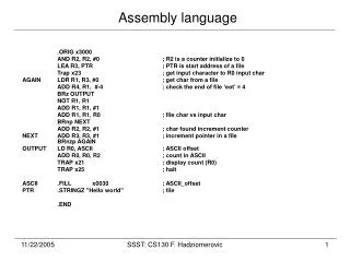
Assembly Language • ARM Cortex-M0+ implements the Thumb instruction set, which is a subset of the instructions supported by more complex cores. • Examples: ; copy the number 2 to r1 MOVS r1,#2 ; subtract r2 from r1 and write the result to r1 SUBS r1, r1, r2 ; copy to r1 the data at the address obtained by adding 0 to the content of r2 LDR r1, [r2, #0] ; copy r2 to the address obtained by adding 0xac to sp. STR r2, [sp, #0xac]
Addressing Modes • The core can address bytes. • 32-bit (word) memory access must be aligned (the address divisible by 4). • 16-bit (half-word) memory access must be aligned (the address divisible by 2). • Instructions can specify addresses by means of offset addressing: ; copy to r1 the 32-bit data at the address obtained by adding 24 to the content of r2 LDR r1, [r2, #24] ; the offset must be divisible by 4 ; copy to r1 the 32-bit data at the address stored in r7 LDR r1, [r7] ; same as LDR r1, [r7, #0] ; copy to r1 the 32-bit data at the address obtained by adding r1 and r2 LDR r1, [r1, r2]
Addressing Modes • Sometimes operands can be specified implicitly by the register name: ; copy r2 to r1 MOVS r1, r2 • Sometimes 8-bit constants may follow immediately: ; copy to r1 the specified number MOVS r1, #59 ; the number must be positive and fit on 8 bits • The ARM manual indicates the addressing modes available to each instruction.
Example The disassembly view of the following program is shown to the left. volatileint x, y, z; x = glb + 0x123456; y = (int)&glb; z = x + y; • glb is a global variable. • The address of glb is written at 0x614. • The address of 0x123456 is 0x618. • R7 has the value of SP. • x is at address r7 + 12. • y is at address r7 + 8. • z is at address r7 + 4.
Branch Instructions • The CPU executes the instructions of a program sequentially, one by one. • However, when the CPU encounters a branch instruction, it jumps to the specified instruction instead of executing the next instruction. • Example:The following shows the implementation of an infinite loop. When the b (branch) instruction is executed, the program returns to the address 0x63e.
Conditional Branch Instructions • Conditional branch instructions are used to implement if-then-else statements. • Conditional branches take place only if the specified condition is true. • An implementation using a conditional branch has two steps: • First, test the condition. Test results should be in the status register APSR. • Second, call the conditional branch. It will read ASPR to determine whether the branch should take place. • Test results should be recorded in the status bits N, Z, V, C of the APSR. • N: negative, Z: zero (equal), V: signed overflow, C: unsigned overflow or no borrow. • (N, Z, V, C are the bits 31, 30, 29, 28 of the register.)
Test Instructions • In general, to make an instruction modify APSR, add the S suffix. • Particularly useful instructions for tests are listed below.
Arithmetic Instructions • The operands and the result are on 32 bits. • The operations work with both signed and unsigned numbers.
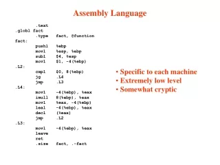
Including Assembly in C via GCC • An asm block may have: • Output operands—C variables that are to be written by the assembly code). • Input operands—C variables that are to be read by the assembly code). • Clobbers—register names and other names informing the compiler about what the assembly code is supposed to modify. • Go to labels—labels of the C program to which the assembly code should jump. • Operands are defined with constraints. • Basic constraints are: • r—the operand should be in a register. • m—the operand should be in memory. • The constraints of output operands begin with = (the operand is written only) or + (meaning the operand is both read and written). • = and + may not be used for the constraints of input operands.
Including Assembly in C—Example volatileint x, y, z, dst, src; asmvolatile ( "ldr r2, %[sr]\n" // copy src to r2 "ldr r1, %[x]\n" // copy x to r1 "mov r3, #0\n" "add r3, r2\n" "str r3, %[ds]\n" // copy r3 to dst "ldr r3, %[y]\n" // copy y to r3 "sub r3, r2\n" "str r3, %[y]\n" // copy r3 to y : [ds] "=m" (dst), [y] "+m" (y) // list output parameters : [sr] "m" (src), [x] "m" (x) // list input parameters : "cc", "r1", "r2", "r3"); // list clobbers // r1, r2, r3 listed because they are modifed; cc states // that condition code (APSR) flags might be modified