Understanding Electromagnetism and Inductance: Advanced Technical Aspects
This course module explores key technical concepts in electromagnetism and inductance, vital for amateur radio enthusiasts. It covers the nature of magnetism, types of magnetic materials, the principles of electromagnetic induction, and how inductance functions in circuits. Participants will learn about soft and hard magnetic materials, Lenz's Law, and the role of inductors and transformers. The course also addresses series and parallel connections of inductors, the significance of the time constant, and practical applications of these concepts in radio technology.

Understanding Electromagnetism and Inductance: Advanced Technical Aspects
E N D
Presentation Transcript
Chelmsford Amateur Radio Society Advanced Course(3) Technical AspectsPart-3 - Inductance, Transformers, Power Supplies
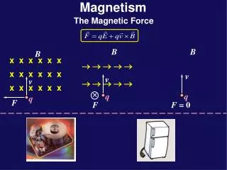
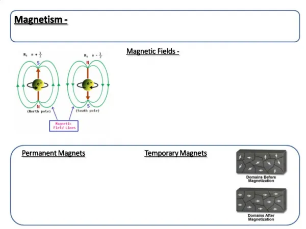
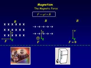
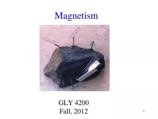
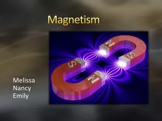
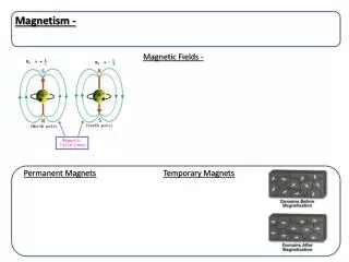
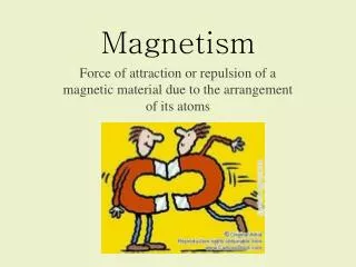
Magnetism • Magnetism is the property by which forces may be set up at a distance to attract certain materials. • Materials are said to be magnetised if they display the following properties:- • When suspended they lay North-South, • Are able to impart magnetism to other materials, • Capable of exerting a force on other magnetised materials. • Materials which are attracted by the force of magnetism are called FERROMAGNETIC • Magnetic Forces can be generated by electric fields
Magnetic Materials • Magnetic materials can be divide into classes • SOFT magnetic materials LOSE the induced magnetism when removed from the field • HARD magnetic material will retain magnetism. • NON FERROMAGNETIC materials have no influence on the field. • Most magnets are based on Iron, Nickel or Cobalt • The ability of a material to concentrate a magnetic field is known as its PERMEABILITY
Electromagnetism • Magnetism is created by the movement of electric charge. • When a current flows in a conductor a magnetic field is produced. • The Magnetic field exists, WITHIN AND AROUND THE CONDUCTOR and weakens as the distance from the conductor increases. • Loops or Coils of wire have a stronger magnetic field in their centre • To produce an intense magnetic field very high currents are required. • It is more usual to have relatively low currents, but many turns • Caution: Unreel main extension coils which can have high currents in
Electromagnets • A coil is wound on a SOFT magnetic core. • With current flowing in the coil the core behaves as a permanent magnet. • The core loses its magnetism when current is switched OFF. • This is called an ELECTROMAGNET. • Ferromagnetic cores are used when strong magnetic fields are required, as the material can concentrate the field lines.
Electromagnetic Induction • Induction occurs when a conductor moves and cuts lines of magnetic flux - the basis of alternators and dynamos • A Voltmeter will give a momentary indication, and current will flow in the circuit. • This is called ELECTROMAGNETIC INDUCTION • The polarity of the induced EMF reverses if either the direction of field or the direction of motion reverses. • The induced EMF is greatest when the conductor moves at rightangles to the magnetic field, and is zero if the conductor moves in line.
Inductance • If a steady current flows there will a steady magnetic field around a conductor and if there is a change in current there will be change in the magnetic field. • A change in the magnetic field will induce a Back EMF in the conductor that will oppose the change being made. (Lenz's Law) and the effect is known as Inductance which has the symbol L • An Inductor is said to have a value of 1 Henry when the current through the conductor changing at a rate of 1 ampere per second induces an EMF of 1 volt. • The Henry is the unit both for self inductance and mutual inductance. • A Henry is rather large so pH, uH and mH are more common
Coils • The self inductance of a wire is small so to increase the inductance the wire is wound in the form of a coil. • The inductance of a coil is dependant on the number of turns, coil area, the permeability of the core of the coil, and spacing between the coil turns. • Coils are wound in various ways depending upon their application. • The value of inductance will vary from several Henries for a power supply filter to a microHenry for a RF circuit. • In RF circuits the inductance can be increased by using non metallic magnetic materials such as ferrites that have a high resistivity and therefore low eddy current loss. • An RF transformer can be adjusted by screwing in a ferrite slug
Mutual Inductance & Back EMF Mutual Inductance & Transformers • When a change in current induces a change in current in another circuit by flux linkage this is called mutual inductance. • Coils that have nearly all lines of flux coupling are tightly coupled. • Coils that are some distance apart and have less flux linkageare loosely coupled. Back EMF • Because of the magnetic field generated by the current flow, changes in this field will induce an EMF in the conductor that will oppose the flow of current. This is known as the back EMF.
Series & Parallel Inductors • Provided that there is no mutual coupling between inductors when they are connected together . . . • SERIES CONNECTION L total = L1 + L2 + L3 etc. • PARALLEL CONNECTION 1/ L total = 1/ L1 + 1/ L2 + 1/L3 etc.
R L V I = V/R Final steady state current I = V/R Time Time t t Decay of Current in Inductor Growth of Current in Inductor LR Time Constant • As with Capacitors, if an Inductance is connected in series with a resistor then there is delay in obtaining the full current/voltage.
LR Time Constant • The LR time constant is defined as . . . • The time in seconds for the current to reach 63.2% of the full value. T = L / R Seconds
Transformer Construction • The property of mutual inductance is employed in transformers which have two windings on a common soft magnetic core • Changes in magnetic flux from an applied voltage in the primary induce a voltage in the secondary windings, BUT they also induce an EMF which can circulate in the magnetic core - EDDY CURRENTS. • Two disadvantages with EDDY Currents are; • Energy is expended in their production, creating losses. • Heat is generated, and overheating can occur. • EDDY CURRENTS are reduced by providing a high resistance path. • Transformers are constructed from thin laminations which are insulated from their neighbours by coats of varnish. At RF, Ferrite is held in a non-conducting binder for the same reason
Ip Is P S Vp Vs Zs Zp Np Turns Ns Turns Transformer Calculations A simple transformer has primary winding P and secondary winding S. Number of turns on the primary = Np Number of turns on the secondary = Ns Voltage across the primary = Vp Voltage across the secondary = Vs • Since both windings are in the same AC magnetic field the induced voltage will be in proportion to the turns on each coil. • The ratio Ns/Np is called the turns ratio. Vs = Vp . Ns / Np Ip = Is . Ns / Np • A Transformer has the property of being able to transform impedance. Zp = Zs . ( Np / Ns ) 2
Peak Inverse Voltage • Peak Inverse Voltage (PIV) is the voltage across the diode when it is not conducting. • This can be twice the peak supply voltage due to the charge on the reservoir capacitor. • Calculated by taking taking the secondary transformer RMS voltage, multiplying by root 2, and then doubling
+V +V Power Supplies - 1 Half Wave Rectification Best suited to low current applications • High Ripple Current and Low Efficiency. • Diode PIV = 2.8 . Vac Full Wave Rectification Circuit also known as Bi-Phase rectification. Each diode conducts on one half cycle. DC component of load flows through the secondary in such a direction to cancel magnetising current. • Diode PIV = 2.8 . Vac
+V Power Supplies - 2 Bridge Rectification Preferred for high voltage, and does not need a centre-tapped transformer. During each half cycle of the input voltage two of the diodes are conducting. • PIV is half per diode. • Diode PIV = 1.4 . Vac
From Rectifier C1 Load L1 From Rectifier C1 C2 Load Smoothing Circuits - 1 Simple Capacitor Filter Capacitor Input Filter
L1 From Rectifier C1 Load R1 From Rectifier C1 C2 Load Smoothing Circuits - 2 Choke Input Filter Resistance Capacitance Filter
Pass Transistor Zener Diode Input Input Output Output IC Regulator Input Output Stabilising Circuits
Screening • Screening is used to prevent coupling between circuits. • Magnetic screens: • A soft magnetic material is introduced to concentrate the flux lines leaving the field weaker elsewhere. Materials such as Mu-metal may be used for this. • Electrostatic screening: • Is when a conductor is surrounded completely by another conductor which has the same potential along its whole length - sometimes called a Faraday Cage • Take care that screens are not too close and unduly influence circuitry they are meant to protect.