Download

1 / 23
230 likes | 234 Views
service repair manual

E N D
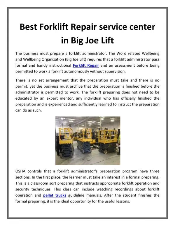
SM-593 GPX/DPX 30/55 Copyrighted Material Intended for CLARK dealers only Do not sell or distribute
Service Manual SM 593 G PXlDPX 30/35/40/405/50/55 Copyrighted Material Intended for CLARK dealers only Do not sell or distribute
Pictorial Index Group 34 - Group 32 Group23 - c Group 25 !- Group 20 Group 22 Group 06 Group 29 Group 38l Group 30 Group 40 +-z) Group 14 Copyrighted Material Intended for CLARK dealers only Do not sell or distribute SM 593, JAN ‘93
CONTENTS Contents of this Manual Group Description Section INTRODUCTION Safety Planned Maintenance ENGINES Engine Removal Diesel Workshop Manual Gas/LPG Workshop Manual 00 00 00 00 1 2 3 01 01 01 01 01 COOLING SYSTEM Troubleshooting Cooling System Testing and Maintenance Fan Belt Replacement Radiator Removal FUEL SYSTEM Fuel Pump Pressure .Test The IMPCO Fuel System Carburetor Overhaul Velocity Governor Overhaul Removal of IMPCO Vaporizing System 02 02 02 02 02 02 TRANSMISSION Transmission Checks Draining and Refill Transmission Removal Transmission Overhaul 06 06 06 06 06 ELECTRICAL SYSTEM Wiring Color Code Wiring Diagrams Electrical Checks 14 14 14 14 1 2 2 DRIVE AXLE Axle End Lubrication Axle End Removal Axle Ends Overhaul Differential Overhaul 20 20 20 20 20 22 22 22 WHEELS AND TIRES Lifting, Jacking, and Blocking Wheels and Tires Mounting 1 2 (continued on next page) Contents-l 0 Clark Material Handling Company 1993 SM 593, JAN ‘93 Copyrighted Material Intended for CLARK dealers only Do not sell or distribute
Section Description Group BRAKING/INCHING SYSTEM System Description/Troubleshooting Brake and Inching System Bleeding Brake and Inching Pedals Adjustment Master Cylinder Overhaul Power Booster Overhaul Brake Caliper Overhaul Parking Brake 23 23 23 23 23 23 23 23 STEERING COLUMN AND GEAR Troubleshooting Steering Column and Gear Removal Char-Lynn Steering Control Unit (Steering gear) 25 25 25 25 1 2 3 STEER AXLE Steer Axle Removal Steer Axle Overhaul Steering System Adjustment Steer Cylinder Removal Steer Axle Wheel Bearings Steer Cylinder Overhaul 26 26 26 26 26 26 26 HYDRAULIC SUMP, FILTERS, AND PUMP Hydraulic Sump and Filters Hydraulic Pump Troubleshooting & Overhaul (Vane Type) 29 29 29 1 2 HYDRAULIC VALVE/LIFT CIRCUIT Hydraulic System Pressure Check Hydraulic Valve Overhaul Hydraulic Valves Hydraulic Schematic 30 30 30 30 30 TILT CYLINDERS Tilt Cylinder Removal Tilt Cylinder Overhaul Tilt Lock Valve 32 32 32 32 1 2 3 UPRIGHTS Troubleshooting and Visual Inspection Operational Checks Carriage Check and Adjsutment Upright Check and Adjustment Cylinder Repair Lift Chain Maintenance Upright Removal and Replacement 34 34 34 34 34 34 34 34 COUNTERWEIGHTS Counterweight Removal and Installation 38 38 1 40 40 40 40 40 40 SPECIFICATIONS Namplates/Decals General Specifications PM Inspection and Drivers Daily Inspection Forms Recommended Lubricants & Lubricant Specifications Lubrication Intervals Copyrighted Material Intended for CLARK dealers only Do not sell or distribute Contents-2 SM 593, JAN ‘93
INTRODUCTION INTRODUCTION Safety ................................................................................. Section 1 Planned Maintenance ........................................................ Section 2 Introduction Copyrighted Material Intended for CLARK dealers only Do not sell or distribute SM 593, JAN ‘93
ElfIRK Introduction Safety 2 Safety Signs and Messages ................................................................................... 2 Practices ........................................................................ User Safe Maintenance Copyrighted Material Intended for CLARK dealers only Do not sell or distribute Safety-l SM 593, Jan ‘93
Introduction Cl!mK A DANGER Safety Signs and Messages Safety signs and messages are placed in this manual and also on the lift truck to provide instructions and to identify specific areas where potential hazards exist and special precautions should be taken. Be sure you know and understand the meaning of these instructions, signs, and messages. Damage to the truck, death, or serious injury to you or other persons may result if these messages are not followed. This message is used when an extreme hazard exists which can result in in- jury or death. or serious injury if proper precautions are not taken. NOTE: The above terms have been adopted by Clark Material Handling Company. The same terms may be used in different context in service literature supplied directly or indirectly by vendors of truck components. NOTICE This message is used when special in- formation, instructions or identifica- tion is required relating to procedures, equipment, tools, pressures, capacities and other special data. User Safe Maintenance Practices The following instructions have been prepared from current industry and government safety standards applicable to industrial truck operation and mainte- nance. These recommended procedures specify con- ditions, methods, and accepted practices that aid in the safe maintenance of industrial trucks. They are listed here for the reference and safety of all workers during maintenance operations. Carefully read and understand these instructions and the specific main- tenance procedures before attempting to do any re- pair work. IMPORTANT This message is used when special pre- cautions should be taken to ensure a correct action or to avoid damage to or malfunction of the truck or a com- ponent. A ! CAUTION When in doubt of any maintenance procedure, please contact your local Clark dealer. This message is used as a reminder of safety hazards which can result in per- sonal injury if proper precautions are not taken. 1. Powered industrial trucks can become haz- ardous if maintenance fore, suitable maintenance personnel, and procedures must be provided. is neglected. facilities, trained There- A WARNING 2. Maintenance industrial trucks shall be done in conform- ance with the manufacturer’s tions. and inspection of all powered This message is used when a hazard exists which can result in injury or death if proper precautions are not taken. recommenda- 3. A scheduled planned maintenance, tion, and inspection lowed. lubrica- program shall be fol- Safety-2 Copyrighted Material Intended for CLARK dealers only Do not sell or distribute SM 593, Jan ‘93
Cl!YRK Introduction 4. d. Stop the engine by turning off the ignition circuit. Only trained and authorized personnel shall be permitted to maintain, repair, adjust, and inspect industrial trucks. Work should be performed in accordance manufacturer’s specifications. e. Put blocks at the wheels if truck is on an incline. with the Brakes, steering mechanisms, control mecha- nisms, warning devices, lights, governors, guards, safety devices, and frame members must be carefully and regularly inspected and maintained in a safe operating condition. 12. 5. Properly ventilate work area, vent exhaust fumes, and keep shop clean and floor dry. Avoid fire hazards and have fire protection equipment present in the work area. Do not use an open flame to check for level or leak- age of fuel, electrolyte, or coolant. Do not use open pans of fuel or flammable fluids for cleaning parts. 6. Special trucks or devices designed and ap- proved for hazardous receive special attention to ensure that main- tenance preserves the original, approved, safe- operating features. 13. area operation must cleaning 7. Before starting work on truck: Fuel systems must be checked for leaks and condition of parts. Extra special consider- ation must be given in the case of a leak in the fuel system. Action must be taken to prevent the use of the truck until the leak has been corrected. 14. a. Raise drive wheels off of floor or discon- nect power source and use blocks or other positive truck positioning devices. b. Disconnect battery before working on the electrical system. Before working on engine fuel system of gasoline- or diesel-powered the fuel shut-off valve is closed. 8. The truck manufacturer’s tion, and maintenance instruction plates, tags, or decals must be maintained in legible con- dition. capacity, opera- 15. trucks, be sure Operation of the truck to check performance must be conducted in an authorized, clear area. 9. safe, Batteries, motors, controllers, limit switches, protective devices, electrical conductors, and connections must be inspected tained in conformance Special attention must be paid to the condi- tion of electrical insulation. 16. 10. Before starting to drive truck: and main- with good practice. a. Be in operating position. b. Be sure parking brake is engaged. Put direction control in neutral. C. To avoid injury to personnel or damage to the equipment, consult the manufacturer’s cedures in replacing contacts on any battery connection. 17. d. Start engine. pro- e. Check functioning of direction and speed controls, steering, brakes, warning de- vices, and any load handling attachments. Industrial condition to minimize fire hazards and help in the detection of loose or defective parts. trucks must be kept in a clean 18. 11. Before leaving ttruck a. Stop truck. b. Put directional control in neutral. Modifications pacity and safe truck operation must not be done without the manufacturer’s ten approval. Capacity, operation and main- and additions that affect ca- 19. c. Apply the parking brake. prior writ- Copyrighted Material Intended for CLARK dealers only Do not sell or distribute Safety-3 SM 593, Jan ‘93
Introduction tenance instruction plates, tags, or decals must be changed accordingly. Care must be taken to assure that all replace- ment parts, including tires, are interchange- able with the original parts and of a quality at least equal to that provided in the original equipment. Parts, including tires, are to be installed per the manufacturer’s Always use genuine CLARK or CLARK- approved parts. 20. procedures. Use special care when removing heavy com- ponents from the truck, such as counterweight, seat deck, upright, etc. Be sure that lifting and handling equipment is of the correct capacity and in good condition. 21. NOTICE You should also be familiar with addi- tional operating safety instructions contained in the fol- lowing publications: and maintenance ANSI/ASME B56.1 - 1988 Operator Control-Indus- trial Tow Tractors (Safety Standard For Powered Industrial Trucks). Published by: Society of Me- chanical Engineers, United Engineering Center, 345 E. 47th Street, New York, NY 10017. NFPA 505- 1982: Fire Safety Standard for Powered Industrial Trucks: Type Designations, Areas of Use, Maintenance and Operation. Available from: Na- tional Fire Protection Assoc., Inc., Batterymarch Park, Quincy, MA 02269. General Industrial Standards, OSHA 2206: OSHA Safety and Health Standards (29 CFR 1910), Sub- part N-Materials Handling and Storage, Section 1910.178 Powered Industrial Trucks. For sale by: Superintendent of Documents, Printing Office, Washington, DC 20402. U.S. Government Copyrighted Material Intended for CLARK dealers only Do not sell or distribute Safety-4 SM 593, Jan ‘93
Group 06, Transmission CLRRK Transmission Removal Drain transmission oil. 8. The transmission removal process described below requires that you first remove the uprights, discon- nect all connections to the transmission, and “drop” the transmission. The engine remains in the truck. The procedure is as follows: Remove bellcrank pin(s) on transmission. from shift linkage(s) at 9. Block the wheels to prevent roll. Then put the direction control in neutral. 1. Using a safety-inspected and approved hoist or other lifting device of adequate capacity, raise truck 12-18 inches (305-457 mm) off floor, as described in Group 22, Section 1, “Lifting, Jacking, and Blocking.” Put wheel cradles of adequate capacity under rear wheels. 2. Put metal or narrow blocks under front frame. Also block under counterweight truck will not tip backward after the upright and transmission are removed. 3. so that the Remove the parking brake yoke pin at the transmission. Remove fasteners attaching park- ing brake cable to transmission case. 10. Remove the uprights as described in Group 34, Section 8, “Upright Removal.” 4. At the transmission inching control valve, dis- connect the inching line that comes from the selector valve. 11. 5. Remove the drive wheels. 6. Unlatch and swing back the hood. Disconnect the battery cables. Inching Line Disconnect 7. Remove the floor plate. Copyrighted Material Intended for CLARK dealers only Do not sell or distribute SM 593, Jan ‘93 06-3-2 ? Transmission Removal
c19Ru= Group 06, Transmission Remove the electric wire leads to the transmis- sion. 15. 12. At the brake line tee (on top of the transmis- sion) that connects the wheel caliper lines to the selector valve line, disconnect the line that goes to the selector valve. Remove the transmission inspection cover so that you can see the bolts that mount the torque converter drive plate to the engine flywheel. 16. Brake Line Disconnect, Inspection Cover Access Port 13. Remove the accelerator cable bracket fasteners from the accelerator pedal attaching bracket and move the accelerator linkage to one side as an assembly. Remove the plug from the drive plate access port in the transmission case, for best access to the bolts that mount the torque converter drive plate to the engine flywheel. 17. Rotate the flywheel so that a torque converter drive plate mounting bolt lines up with the access port. With an extension through the access port, unscrew the bolt from the fly- wheel. Repeat for each bolt. 18. Bracket Fastener NOTICE 14. Disconnect two transmission oil cooling lines: At the transmission control cover, disconnect the line that goes to the radiator. At the tee on the transmission, disconnect the line that goes to the oil filter. Do not pry on the torque converter. Nicks and scratches on the convertor housing could lead to fatigue of the metal and eventual leaks. Disconnect Bolt to ’ Disconnect / Engine Flywheel Copyrighted Material Intended for CLARK dealers only Do not sell or distribute SM 593, Jan ‘93 Transmission Removal ? 06-3-3
Group 06, Transmission Transmission Installation 19. Use a lift truck or safety-inspected proved lifting device to support the transmis- sion and use a jack to support the engine bell housing. and ap- The following is a continuation of the process, de- scribed above, by which the transmission “dropped” from the truck with the engine left in. The instructions below first cover installation of the torque converter into the transmission, then installation of the transmission into the truck. was 20. Remove bolts that attach transmission to en- gine bell housing. (See illustration in step 22.) 21. Remove bolts attaching transmission and dif- ferential to frame. Make sure truck blocking is secure and cor- rectly positioned, raising truck 12-18 inches (305-457 mm) off floor. 1. Transmission Mounting Bolt Make sure transmission is secure on the lifting device and that the insertion area beneath the truck is clear of obstacles and blocking. 2. Remove the transmission inspection cover so that you can see inside to mount the torque converter drive plate to the engine flywheel. Also remove the access port plug. You will bolt the torque converter drive plate to the engine flywheel through this port. 3. CAUTION Make sure blocking is not disturbed when the transmission is removed. 22. Gradually pull the transmission from the en- gine and lower it. Make sure that all connec- tions to the transmission are free as you lower. NOTICE Keep inspection opening covered with a clean shop rag to prevent foreign material from getting inside transmis- sion case. 4. Make sure the torque converter drive plate is bolted to the torque converter. (See illustration in step 1 l-c.) Fastener torque is 28-32 lbf-ft (37.9-43.4 Nmm). Copyrighted Material Intended for CLARK dealers only Do not sell or distribute 06-3-4 ? Transmission Removal SM 593, Jan ‘93
Cl!!mK Group 06, Transmission 11. Bolt the torque converter drive plate to the engine flywheel as follows: 5. Lubricate the seal and bearing surface of the transmission stator support to let the tang drive of the convertor slide into the convertor pump drive gear tangs. a. Rotate the torque converter drive plate so that a mounting bolt hole lines up with the access port. b. Rotate the engine flywheel so that a mount- ing bolt hole lines up with the access port. NOTICE Do not pry on the torque converter. Nicks and scratches on the convertor housing could lead to fatigue of the metal and eventual leaks. Gear 6. Vlake sure the convertor pump drive gear is :orrectly positioned on the stator support. c. Place a mounting bolt with washer in an appropriate magnetic socket so that the rounded-edge side of the washer will con- tact the torque converter drive plate. 7. Carefully insert the torque convertor drive shaft into the stator support. Rotate the transmission gearing to align the tangs on the convertor shaft; and push the convertor so its tangs drop into the gear tangs. 8. Replace the gasket, and carefully insert trans- 1 mission assembly into position with the en- gine. Housing Mounting \ 6 \ Flywheel Washer (Rounded Edges against Plate) With the socket on an extension, insert the mounting bolt through the access port and through the torque converter drive plate. Start the bolt into the engine flywheel. d. Repeat for each mounting bolt. Tighten the bolts gradually, making several rotations of the drive plate/flywheel. Final torque for each bolt should be 19-21 lbf-ft (25.8-28.5 Nom). e. 9. Check that the torque converter is free to rotate with the flywheel. NOTICE 10. Insert the bolts joining the transmission hous- ing to the engine bell housing. Tighten the fasteners to a torque of (33-37 Nom) 24-27 lbf-ft. If a drive plate mounting bolt falls into the transmission case, it must be removed to avoid eventual destruc- tion of the transmission. Copyrighted Material Intended for CLARK dealers only Do not sell or distribute ? 06-3-5 SM 593, Jan ‘93 Transmission Removal
Group 06, Transmission El!!WK Replace the inspection cover on the transmis- sion and tighten the fasteners to a torque of 24- 27 lbf-ft. (33-37 Nom). 12. Install hoist on front of engine. 19. Raise engine until all 10 transmission mount- ing bolts freeplay out of bolt holes. 20. 13. Replace the inspection port plug. Add shims (flat washers) under front engine mounts, if necessary, and loosely reinstall the engine mounting bolts. 21. 14. Remove the jack or blocking supporting the engine bell housing. 15. Align center hole on each side of frame and differential housing. lockwasher on each side and tighten to “finger tight” torque. 22. Let down hoist. Install one bolt and Torque all transmission mounting bolts to (550 Nom) 405-515 lbf-ft. Torque both engine mounting bolts to 23-27 lbf-ft (32-36 Nom). 23. Replace the electric wire leads to the transmis- sion. 24. Connect two transmission oil cooling lines: At the transmission control cover, connect the line that goes to the radiator. At the tee on the transmission, connect the line that goes to the oil filter. Be sure of correct assembly. Tighten connectors to a torque of (25-27 Nom) 18-20 lbf-ft. 25. Connect ----- 16. Add shims to right and left side side to fill void. 17. Start all 10 transmission mounting bolts (with lockwashers), but do not tighten. Loosen two front engine mounting bolts. 18. At the transmission inching control valve, con- nect the inching line that comes from the selec- tor valve. 26. Engine , Mounting Bolt Inching Line Connection Washer/Shim - Copyrighted Material Intended for CLARK dealers only Do not sell or distribute 06-3-6 SM 593, Jan ‘93 ? Transmission Removal
CMRK Group 06, Transmission 27. At the brake line tee (on top of the transmis- sion) that connects the wheel caliper lines to the selector valve line, connect the line that goes to the selector valve. Install the connecting pin(s) in shift linkage yoke(s) at bellcrank cotter pin(s) and bend legs on cotter pin(s). 30. on transmission. Insert Brake Line Disconnect. 28. Move the accelerator linkage into position and install the accelerator cable bracket fasteners into the accelerator pedal attaching bracket. Torque fasteners to 83-94 lbf-in (9-l 1 N=m). Replace the upright as described in Group 34, Section 8, “Upright Removal.” 31. Fill transmission with correct fluid. 32. Fill hydraulic sump tank to correct level with proper fluid. 33. Install battery and tighten battery terminal nuts to a torque of 170-191 lbf-in (19-22 Nom). Make sure terminal boots are fnmly in place. 34. Start truck, allow fluids to circulate, and shut off truck. 35. Bracket Fastener Recheck fluid transmission and hydraulic fluid levels. 36. 29. Replace fasteners attaching parking brake cable to transmission case. Replace the parking brake yoke pin and cotter pin. Spread cotter pin ends. Bleed the inching lines and bleed the brake lines from the wheel caliper to the power boost- ers, as described in Group 23, Section 2, “Brake and Inching System Bleeding.” 37. Install the floor plate and tighten the fasteners. 38. Mount drive wheels on axle ends. Tighten wheel nuts to a torque of 450-500 lbf-ft (610-678N.m). 39. Carefully raise truck using approved equip- ment of adequate capacity and remove block- ing. 40. Yoke Pin Copyrighted Material Intended for CLARK dealers only Do not sell or distribute Transmission Removal ? 06-3-7 SM 593, Jan ‘93
Group 06, Transmission Cl!ARK Make sure all warning decals are in place. 40. Carefully check all operating controls in accor- dance with operator manual. 41. Check for any binding in control linkages and make sure all controls return to position when released. 42. Operate truck slowly and listen for any unusual noise in transmission. Make sure truck responds correctly to forward/reverse shifts, and to low/ high shifts if 2-speed. 47. Copyrighted Material Intended for CLARK dealers only Do not sell or distribute SM 593, Jan ‘93 06-3-8 ? Transmission Removal
Group 06, Transmission Cl!!YRK HYDRATORK TRANSMISSION TWO SPEED FWD AND REV MODELS HZ00 THRU H213: SINGLE SPEED AND When the Hydratork transmission is disassembled, the following steps must be carefully followed for correct operation of the transmission. arrow shows the location of the model and part numbers. The 1. Remove the torque convertor. 2. Remove all fasteners from the axle adaptor to transmission. Separate the adaptor from the transmission by using jackscrews. Remove the axle adaptor assembly. 3. Remove the axle adaptor adjustment shim(s) and the O-ring seal. 1 n772 Copyrighted Material Intended for CLARK dealers only Do not sell or distribute 06-4-2 ? Transmission Overhaul SM 593, Jan ‘93
CMRK Group 06, Transmission 4. Remove the convertor pump from the trans- mission assembly. 10224 5. Remove the control cover assembly and gasket. 10225 6. Install the control cover capscrews into the oil sleeves. After the capscrews are in place, lift up on the capscrews (while holding the oil tubes) to prevent damage to the tubes. 10226 7. Remove the forward and reverse oil tubes. Copyrighted Material Intended for CLARK dealers only Do not sell or distribute SM 593, Jan ‘93 Transmission Overhaul ? 06-4-3
Thank you very much for your reading. Please Click Here. Then Get COMPLETE MANUAL. NO WAITING NOTE: If there is no response to click on the link above, please download the PDF document first and then click on it.
EL’YRK Group 06, Transmission Remove the high and low oil tubes. 8. NOTE Single speed speed transmission does not have hi and lo clutches as shown in photo. 10228 Remove the speed selector oil distributor retainer ring. 9. 10234 10. Remove the speed selector oil distributor by pulling out from the transmission. 10235 11. Use soft brass stock to keep the gears from moving. 10236 Copyrighted Material Intended for CLARK dealers only Do not sell or distribute 06-4-4 ? Transmission Overhaul SM 593, Jan ‘93
Cl!lRK Group 06, Transmission 12. Remove the output shaft retainer. Fig. 10383 13. Use a soft brass bar to remove the output shaft from the converter end toward the axle adaptor end. Fig. 10237 14. After the shaft has been moved toward the axle adaptor end, remove the gear, spacer and thrust washer. Continue to move the shaft until the shaft assembly is away from the clutch pack. Fig. 10238 Copyrighted Material Intended for CLARK dealers only Do not sell or distribute SM 593, Jan ‘93 Transmission Overhaul ? 06-4-5
Group 06, Transmission Fig. 10244 (Output Shaft Assembly) 15. Remove the transmission input shaft cap on the axle adaptor end of the transmission. Later model transmissions do not have this o-ring seal (a). Fig. 10229 ? Transmission Overhaul SM 593, Jan ‘93 Copyrighted Material Intended for CLARK dealers only Do not sell or distribute 06-4-6