Download

1 / 19

E N D
www.WorkshopManuals.co.uk Operator Handbook J CB 1CX From serial number 751600 to 752999 and from 806000 Onwards !THIS HANDBOOK MUST BE KEPT IN THE MACHINE AT ALL TIMES ! Publication Number 9801/4230 April 2002 Issue 14 Purchased from www.WorkshopManuals.co.uk
www.WorkshopManuals.co.uk SAFETY NOTICES In this handbook and on the machine there are safety notices. Each notice starts with a signal word. The meanings of the signal words are given below. ! DANGER Denotes an extreme hazard exists. If proper precautions are not taken, it is highly probable that the operator (or others) could be killed or seriously injured. INT-1-2-1 ! WARNING Denotes a hazard exists. If proper precautions are not taken, the operator (or others) could be killed or seriously injured. INT-1-2-2 ! CAUTION Denotes a reminder of safety practices. Failure to follow these safety practices could result in injury to the operator (or others) and possible damage to the machine. INT-1-2-3 ! WARNING Study This Handbook Before Starting The Machine You must understand and follow the instructions in this handbook. You must observe all relevant laws and regulations. If you are unsure about anything, ask your JCB distributor or employer. Do not guess, you or others could be killed or seriously injured. INT-1-1-1 ! CAUTION Do not fit an attachment to this machine which is not JCB approved. Consult your JCB distributor before fitting any non approved attachment. 8-4-1-6 MACHINE SECURITY Vandalism and theft of unattended machines is an ever increasing problem and JCB is doing everything possible to help combat this. JCB PLANTGUARD is a comprehensive package available to help you safeguard your machine. It includes such devices as vandal proof covers, window etching, immobiliser, concealed serial number, battery isolator, Tracker security system and much more. Remember that the fitting of any one of these security devices will help to minimise not only the damage or loss of your machine but also subsequent lost productivity. It could also result in reduced insurance premiums. Your JCB Distributor or Dealer will be pleased to provide information on any of these sensible precautions. ACT NOW! INT-1-2-4 4230-1 Purchased from www.WorkshopManuals.co.uk
www.WorkshopManuals.co.uk CONTENTS i i INTRODUCTION Page Page About this Handbook Machine Models ........................................................ Location of Handbook ............................................... 1 Using this Handbook ................................................. 1 Units of Measurement ............................................... Page Numbering ....................................................... Left Side, Right Side ................................................. Using the Machine .................................................... Seat Controls ......................................................... 31 1 Loader Controls Loader Arm/Shovel Control Lever .............................. Auxiliary Attachments Control Switches ..................... 32 Auxiliary Attachments Detent Switch .......................... 32 High-flow Hydraulic Switch ......................................... 32 Float Control Switch ................................................... 32 31 1 1 1 1 The J CB 1CX Machine Description ................................................. 2 Stabiliser Controls ................................................... 33 Backhoe Controls (J CB X Pattern) J CB X Pattern .......................................................... 34 Boom and Slew Movements .................................... 35 Dipper and Bucket Movements ............................... 36 Safety First - Yours and Other People's ............... 3 Safety Check List General Safety .......................................................... Operating Safety ....................................................... Maintenance Safety .................................................. 3 4 5 Backhoe Controls (J CB + Pattern) J CB + Pattern .......................................................... 37 Boom and Slew Movements .................................... 38 Dipper and Bucket Movements ............................... 39 Safety Decals .......................................................... 6 Identifying Your Machine Machine Identification Plate ...................................... Typical Vehicle Identification Number (VIN) ............... Unit Identification ...................................................... Backhoe Controls (ISO Pattern) ISO Pattern ............................................................. Dipper and Slew Movements .................................. Boom and Bucket Movements ................................ 42 8 8 8 40 41 J CB Immobiliser Option ......................................... 9 Hydraclamps ......................................................... 43 Foot Operated Pedal ............................................ 43 OPERATION Before Starting the Engine .................................. 44 Introduction ............................................................ 21 Starting the Engine ............................................... 45 Before Entering the Cab ........................................ 21 J ump-Starting the Engine .................................... 46 Entering/Leaving the Cab ....................................... Backhoe Control Lever Lock .................................... 23 Leaving the Cab in an Emergency ........................... 22 Preparing the Machine for Travel Travelling on Site .................................................... Travelling on the Road ............................................. 48 Travelling on the Road (UK only) .............................. 47 23 48 Cab Light (Cab Machines only) .............................. 23 Boom/Slew Lock Engage the Boom/Slew Lock .................................... 50 Release the Boom/Slew Lock ................................... 50 Door and Windows (Cab Machines only) ............. 24 Seat Belt Fastening the Seat Belt ........................................... Releasing the Seat Belt ........................................... Checking Seat Belt Operation ................................. 25 25 25 Rotating Beacon .................................................... 51 Testing the Parking Brake ..................................... 51 Cab Layout ............................................................. 26 Getting the Machine Moving Drive Control Lever .................................................... 52 Operating Procedures ............................................... 52 Getting Moving ......................................................... 53 Heater Controls (Cab Machines only) ................... 28 Switches and Instruments Switches .................................................................... Warning Indicators ................................................... 30 Hourmeter ................................................................ 30 28 Stopping and Parking the Machine ...................... 53 Using the Attachments and Site Safety ............... 54 4230-8 Purchased from www.WorkshopManuals.co.uk
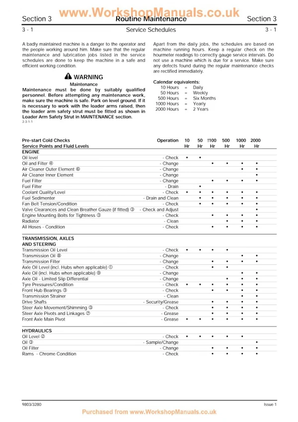
www.WorkshopManuals.co.uk CONTENTS ii ii OPERATION cont'd Page Page ............................................ 75 Cleaning the Machine Loader Quickhitch Engaging the Shovel/Attachments ........................... 56 Disengaging the Shovel/Attachments ...................... 57 ............................................ 75 Checking for Damage ROPS/FOPS Structure Checking the ROPS/FOPS Structure ....................... 75 Working with the Loader Filling the Shovel ...................................................... 58 Loading a Truck ........................................................ 58 Scraping and Cutting ................................................ 58 Loader Arm Safety Strut Installing the Safety Strut ......................................... 76 Removing the Safety Strut ....................................... 76 Working with the Backhoe Removing a Bucket .................................................. 59 Fitting a Bucket ........................................................ 59 Preparing to Use the Backhoe ................................. 60 Digging ..................................................................... 60 Moving the Machine While Digging .......................... 61 Digging Near Walls .................................................. 61 Digging on Slopes ................................................... Engine Compartment Access Opening and closing the Bonnet .............................. 77 Removing and Fitting a Side Panel .......................... 77 ......................................... 77 Removing Floor Plates 61 Seat Belt Checking Seat Belt Condition and Security ............. 78 ...................................... 62 Sideshifting the Backhoe ........................... 63 Greasing (10 Hours) Quickhitch Pivot Points ............................................ 78 Loader Arm Pivot Points .......................................... 79 Backhoe ................................................................... 80 Operating in Low Temperatures .......................... 63 Operating in High Temperatures Transporting the Machine Using a Truck .......................................................... Using a Trailer ......................................................... Transportation Safety .............................................. 64 64 65 Lubrication Oiling Control Levers ............................................... Oiling Door Hinges (Cabbed Machines) .................. Checking Slew Oil Level .......................................... 81 81 81 ................................. 65 Moving a Disabled Machine Engine Air Filter Changing the Elements ............................................ .............................. 66 82 Emergency Lower Procedure Engine Oil and Filter Checking the Oil Level ............................................ Changing the Oil and Filter ..................................... MAINTENANCE 83 83 Lubricants - Health and Safety Hygiene .................................................................... 71 Storage .................................................................... Waste Disposal ........................................................ 71 Handling ................................................................... 71 First Aid - Oil ............................................................ 71 Spillage .................................................................... 71 Fires ......................................................................... 71 Engine Cooling System Coolant Mixtures ..................................................... Checking the Coolant Level .................................... Changing the Coolant ............................................. Cleaning the Coolant Radiator ................................ 85 85 86 86 71 Engine Alternator Belt Checking the Alternator Belt Tension ..................... Adjusting the Alternator Belt ................................... 87 87 ........................................... 72 Service Requirements Drive Chain Lubrication Checking the Oil Levels .......................................... Service Schedules Every 10 Operating Hours or Weekly (first 50 operating hrs. only) ...................................... 73 Every 10 Operating Hours or Daily .......................... 73 After the First 50 Operating Hours only ................... Every 50 Operating Hours or Weekly ...................... Every 100 Operating Hours or 2 Weekly ................. Every 250 Operating Hours or Monthly ................... Every 500 Operating Hours or 6 Monthly ................ Every 1000 Operating Hours or Yearly .................... 74 Every 2000 Operating Hours or 2 Yearly ................. 74 88 Fuel System Types of Fuel ........................................................... 89 Fuel Standards ........................................................ Low Temperature Fuels ........................................... 89 Petrol ....................................................................... Advice ...................................................................... 89 Filling the Tank ........................................................ Draining the Fuel Filter .............................................. Changing the Fuel Filter Element ............................. 73 73 74 74 74 89 89 89 90 90 4230-4 Purchased from www.WorkshopManuals.co.uk
www.WorkshopManuals.co.uk CONTENTS iii iii MAINTENANCE cont'd OPTIONAL ATTACHMENTS Page Page Hydraulic System Checking the Fluid Level .......................................... 91 Changing the Filter ................................................... 91 Introduction .......................................................... 111 Quick Release Couplings .................................... 112 Battery Safety ....................................................................... 92 Warning Symbols ..................................................... 93 Checking the Electrolyte Level ................................. 93 Connecting/Disconnecting Hydraulic Hoses ........ 112 Shovels General Purpose and Light Duty Shovels ................. 114 Electrical System Fuses ....................................................................... Relays ...................................................................... Light Bulbs ............................................................... 94 6-in-1 Shovel ............................................................ 115 94 94 Pallet Forks .............................................................. 117 Manure/Silage Fork with Top Grab ........................ 118 Tyres and Wheels Inflating the Tyres .................................................... Renewing Segments of Optional Non-Inflatable Tyres Checking the Wheel Bolt Torques ........................... 95 95 95 Attachment Frame ................................................... 120 Backhoe Quickhitch ............................................... 121 Installing the Quickhitch ........................................... 121 Removing the Quickhitch ......................................... 121 Maintenance ............................................................ Installing Backhoe Quickhitch Attachments ............. 122 Removing Backhoe Quickhitch Attachments ........... 124 Windscreen Washer .............................................. 96 121 Fluids, Capacities and Lubricants ....................... 97 Obtaining Replacement Parts .............................. 97 SPECIFICATION Storage ..................................................................... 98 Static Dimensions and Specifications .................. 131 Optional Attachments ........................................... 133 Noise and Vibration Data ..................................... 134 Tipping Loads ....................................................... 134 4230-8 Purchased from www.WorkshopManuals.co.uk
www.WorkshopManuals.co.uk INTRODUCTION 1 1 ABOUT THIS HANDBOOK Machine Models Units of Measurement This handbook provides information for the JCB 1CX machine from serial number 751600 to 752999 and from 806000 onwards. In this handbook, the S.I. system of units is used. For example, liquid capacities are given in litres. The Imperial units follow in parenthesis () eg 28 litres (6 gal). Location of Handbook Page Numbering The handbook is located in a pocket on the seat back, as at A. The handbook should always be returned to its correct stowage. The page numbering system in this handbook is not continuous. There is a gap between sections. This allows for the insertion of new pages in later issues of the handbook. Using this Handbook Left Side, Right Side The illustrations in this handbook are for guidance only. Where the machines differ, the text and/or the illustration will specify. In this handbook, unless otherwise specified in the text, 'left' and 'right' mean your left and right when you are seated in the machine facing the loader end as shown at B. The only exception to this is in 'Backhoe Controls' in OPERATION section. This is because you will be facing the backhoe (rear) end of the machine, as shown at C, when operating these controls and your left and right are reversed. This handbook is arranged to give you a good understanding of the machine and its safe operation. It also contains maintenance information and specification data. Read this handbook from front to back before using the machine for the first time. Particular attention must be given to all the safety aspects of operating and maintaining the machine. Using the Machine General warnings in this chapter are repeated throughout the book, as well as specific warnings. Read all the safety statements regularly, so you do not forget them. Remember that the best operators are the safest operators. To use the 1CX efficiently and safely you must know the machine and have the skill to use it. This handbook instructs you on the machine, its controls and its safe operation. It is not a training manual on the art of loading and excavating. If you are a new operator, get yourself trained in the skills of using a 1CX before trying to work with it. If you do not, you will not do your job well, and you will be a danger to yourself and others. Finally, treat this handbook as part of the machine. Keep it clean and in good condition. Do not operate the machine without a handbook in the cab. If there is anything you are not sure about, ask your JCB distributor or employer. Do not guess, you or others could be killed or seriously injured. The manufacturer's policy is one of continuous improvement. The right to change the specification of the machine without notice is reserved. No responsibility will be accepted for discrepancies which may occur between specifications of the machine and the descriptions contained in this publication. INT-1-2-5/1 B A C S202361 S202340 4230-2 Purchased from www.WorkshopManuals.co.uk
www.WorkshopManuals.co.uk INTRODUCTION 2 2 THE JCB 1CX Machine Description The 1CX is a self propelled wheeled skid steer machine with a main structural support designed to carry both a front mounted bucket loading mechanism and a rear mounted backhoe. When used in the backhoe mode, the machine normally digs below ground level with bucket motion towards the machine; the backhoe lifts, swings and discharges material while the machine is stationary. When used in the loader mode, the machine loads or excavates through forward motion of the machine, and lifts, transports and discharges material. BEACON FRONT WORK LIGHT LOADER ARM LOADER SHOVEL DRIVE CONTROLS S202351 REAR WORK LIGHT DIPPER LOADER CONTROLS EXCAVATOR CONTROLS BUCKET S202361 4230-1 Purchased from www.WorkshopManuals.co.uk
www.WorkshopManuals.co.uk INTRODUCTION 3 3 SAFETY FIRST - YOURS AND OTHER PEOPLE'S All construction and agricultural equipment can be hazardous. When a 1CX is correctly operated and properly maintained, it is a safe machine to work with. But when it is carelessly operated or poorly maintained it can become a danger to you (the operator) and others. Do not work with the machine until you are sure that you can control it. Do not start any job until you are sure that you and those around you will be safe. In this handbook and on the machine you will find warning messages. Read and understand them. They tell you of potential hazards and how to avoid them. If you do not fully understand the warning messages, ask your employer or JCB distributor to explain them. If you are unsure of anything, about the machine or the job, ask someone who knows. Do not assume anything. Remember BE CAREFUL BE ALERT BE SAFE But safety is not just a matter of responding to the warnings. All the time you are working on or with the machine you must be thinking what hazards there might be and how to avoid them. INT-1-3-1/1 SAFETY CHECK LIST General Safety ! Handbook You and others can be injured if you operate or maintain the machine without first studying this handbook. Read the safety instructions before operating the machine. If you do not understand anything, ask your employer or JCB distributor to explain it. Keep this handbook clean and in good condition. Do not operate the machine without a handbook in the cab, or if there is anything on the machine you do not understand. INT-1-3-2 ! Regulations Obey all laws, work site and local regulations which affect you and your machine. INT-1-3-3 ! Decals You can be injured if you do not obey the decal safety instructions. Keep decals clean. Replace unreadable or missing decals with new ones before operating the machine. Make sure replacement parts include warning decals where necessary. INT-1-3-4 ! Care and Alertness All the time you are working with or on the machine, take care and stay alert. Always be careful. Always be alert for hazards. INT-1-3-5 ! Raised Attachments Raised attachments can fall and injure you. Do not walk or work under raised attachments unless they are safely blocked. INT-1-3-8 ! Clothing You can be injured if you do not wear the proper clothing. Loose clothing can get caught in the machinery. Wear protective clothing to suit the job. Examples of protective clothing are: a hard hat, safety shoes, safety glasses, a well fitting overall, ear- protectors and industrial gloves. Keep cuffs fastened. Do not wear a necktie or scarf. Keep long hair restrained. INT-1-3-6 ! Lifting Equipment You can be injured if you use faulty lifting equipment. Make sure that lifting equipment is in good condition. Make sure that lifting tackle complies with all local regulations and is suitable for the job. Make sure that lifting equipment is strong enough for the job. INT-1-3-7 ! Alcohol and Drugs It is extremely dangerous to operate machinery when under the influence of alcohol or drugs. Do not consume alcoholic drinks or take drugs before or whilst operating the machine or attachments. Be aware of medicines which can cause drowsiness. INT-1-3-9 ! Machine Modifications This machine is manufactured in compliance with legislative and other requirements. It should not be altered in any way which could affect or invalidate any of these requirements. For advice consult your JCB Distributor. Reference should also be made to Optional Attachments section where appropriate. INT-1-3-10 4230-1 Purchased from www.WorkshopManuals.co.uk
www.WorkshopManuals.co.uk INTRODUCTION 4 4 SAFETY CHECK LIST (continued) Operating Safety ! Practice You or others can be killed or seriously injured if you do unfamiliar operations without first practising them. Practise away from the work site on a clear area. Keep other people away. Do not perform new operations until you are sure you can do them safely. INT-2-1-1 ! Machine Condition A defective machine can injure you or others. Do not operate a machine which is defective or has missing parts. Make sure the maintenance procedures in this handbook are completed before using the machine. INT-2-1-2 ! Controls You or others can be killed or seriously injured if you operate the control levers from outside the cab. Operate the controls levers only when you are correctly seated inside the cab. INT-2-1-3 ! Machine Limits Operating the machine beyond its design limits can damage the machine, it can also be dangerous. Do not operate the machine outside its limits. Do not try to upgrade the machine performance with unapproved modifications. INT-2-1-4 ! Rollover Should the machine start to roll over, you can be crushed if you try to leave the cab. If the machine starts to roll over, DO NOT TRY TO JUMP FROM THE CAB. STAY IN THE CAB, WITH YOUR SEAT BELT FASTENED. INT-2-1-12 ! ROPS/FOPS Structure The machine is fitted with a Roll Over Protection Structure (ROPS) and a Falling Objects Protection Structure (FOPS). You could be killed or seriously injured if you operate the machine with a damaged or missing ROPS/FOPS. If the ROPS/FOPS has been in an accident, do not use the machine until the structure has been renewed. Modifications and repairs that are not approved by the manufacturer may be dangerous and will invalidate the ROPS/FOPS certification. INT-2-1-9/3 ! Seat Belts The ROPS/FOPS cab is designed to give you protection in an accident. If you do not wear your seat belt, you could be thrown around inside the cab or thrown out of the machine and crushed. You must wear a seat belt when using the machine. Fasten the seat belt before starting the engine. 2-2-1-9 ! Cold Starting Do not use ether or other starting fluids to assist cold starting. Using these fluids may result in an explosion causing possible injury and/or damage to the engine. 3-2-1-9 ! Exhaust Gases Breathing the machine exhaust gases can harm and possibly kill you. Do not operate the machine in closed spaces without making sure there is good ventilation. If possible, fit an exhaust extension. If you begin to feel drowsy, stop the machine at once. Get out of the cab into fresh air. INT-2-1-10 ! Hazardous Atmospheres This machine is designed for use in normal out door atmospheric conditions. It should not be used in an enclosed area without adequate ventilation. Do not use the machine in a potentially explosive atmosphere, i.e. combustible vapours, gas or dust, without first consulting your JCB Distributor. INT-2-1-14 ! Visibility Accidents can be caused by working in poor visibility. Keep windows clean and use your lights to improve visibility. Do not operate the machine if you cannot see properly. INT-2-1-11 ! Passengers Passengers in or on the machine can cause accidents. The JCB Skid Steer Loader is a one man machine. Do not carry passengers. INT-2-2-2 ! Ramps and Trailers Water, mud, ice, grease and oil on ramps or trailers can cause serious accidents. Make sure ramps and trailers are clean before driving onto them. Use extreme caution when driving onto ramps and trailers. Always reverse up a ramp if unloaded, travel forwards if loaded. Always reverse down a ramp if loaded, travel forwards if unloaded. 3-1-1-3/1 ! Sparks Explosions and fire can be caused by sparks from the exhaust or the electrical system. Do not use the machine in closed areas where there is flammable material, vapour or dust. INT-2-2-10 ! Safe Working Loads Overloading the machine can damage it and make it unstable. Study the lifting and/or digging specifications in this handbook before using the attachments. INT-2-2-11/1 4230-1 Purchased from www.WorkshopManuals.co.uk
www.WorkshopManuals.co.uk INTRODUCTION 5 5 SAFETY CHECK LIST (continued) Maintenance Safety ! Repairs Do not try to do repairs or any other type of maintenance work you do not understand. Get a Service Manual from your JCB distributor, or get the work done by a specialist engineer. INT-3-1-1 ! Modifications and Welding Non-approved modifications can cause injury and damage. Parts of the machine are made from cast iron; welds on cast iron can weaken the structure and break. Do not weld cast iron. Contact your JCB distributor for advice before modifying the machine. INT-3-1-2/1 ! Metal Splinters You can be injured by flying metal splinters when driving metal pins in or out. Use a soft faced hammer or drift to remove and fit metal pins. Always wear safety glasses. INT-3-1-3 ! Communications Bad communications can cause accidents. If two or more people are working on the machine, make sure each is aware of what the others are doing. Before starting the engine make sure the others are clear of the danger areas; examples of danger areas are: the rotating blades and belt on the engine, the attachments and linkages, and anywhere beneath or behind the machine. People can be killed or injured if these precautions are not taken. INT-3-1-5 ! Soft Ground A machine can sink into soft ground. Never work under a machine on soft ground. INT-3-2-4 ! Raised Machine NEVER position yourself or any part of your body under a raised machine which is not properly supported. If the machine moves unexpectedly you could become trapped and suffer serious injury or be killed. INT-3-3-7/1 ! Petrol Do not use petrol in this machine. Do not mix petrol with the diesel fuel; in storage tanks the petrol will rise to the top and form flammable vapours. INT-3-1-6 ! Diesel Fuel Diesel fuel is flammable; keep naked flames away from the machine. Do not smoke while refuelling the machine or working on the engine. Do not refuel with the engine running. There could be a fire or injury if you do not follow these precautions. INT-3-2-2 ! Oil Oil is toxic. If you swallow any oil, do not induce vomiting, seek medical advice. Used engine oil contains harmful contaminants which can cause skin cancer. Do not handle used engine oil more than necessary. Always use barrier cream or wear gloves to prevent skin contact. Wash skin contaminated with oil thoroughly in warm soapy water. Do not use petrol, diesel fuel or paraffin to clean your skin. INT-3-2-3 ! Electrical Circuits Understand the electrical circuit before connecting or disconnecting an electrical component. A wrong connection can cause injury and/or damage. INT-3-1-4 Do not disconnect the battery while the engine is running otherwise the electrical circuits may be damaged. INT-3-1-14 Do not switch the battery isolator to OFF while the engine is running. Failure to comply may result in damage to the electrical circuits. 4-2-1-7 ! Arc Welding Before carrying out arc welding on the machine, disconnect the battery and alternator to protect the circuits and components. The battery must still be disconnected even if a battery isolator is fitted. Make sure that the welding earth return path is kept as short as possible. This prevents high currents being induced in the machine chassis or wiring harnesses. If the machine is equipped with amplifier drivers or electronic control units (E.C.U.s) then disconnect them before welding. Failure to disconnect the amplifier drivers or E.C.U.s could result in irreparable damage to the electronic components. INT-3-1-15/1 ! Fires If your machine is equipped with a fire extinguisher, make sure it is checked regularly. Keep it in the operator's cab until you need to use it. Do not use water to put out a machine fire, you could spread an oil fire or get a shock from an electrical fire. Use carbon dioxide, dry chemical or foam extinguishers. Contact your nearest fire department as quickly as possible. Firefighters should use self- contained breathing apparatus. INT-3-2-7/1 4230-2 Purchased from www.WorkshopManuals.co.uk
www.WorkshopManuals.co.uk INTRODUCTION 6 6 SAFETY CHECK LIST (continued) Maintenance Safety (continued) ! Hydraulic Fluid Fine jets of hydraulic fluid at high pressure can penetrate the skin. Do not use your fingers to check for hydraulic fluid leaks. Do not put your face close to suspected leaks. Hold a piece of cardboard close to suspected leaks and then inspect the cardboard for signs of hydraulic fluid. If hydraulic fluid penetrates your skin, get medical help immediately. INT-3-1-10/1 ! Hydraulic Pressure Hydraulic fluid at pressure can injure you. Make the machine safe before connecting or disconnecting quick release couplings; stop the engine then turn the starter switch to IGN and operate the auxiliary attachment control switch a few times to vent residual hydraulic pressure in the attachment hoses. 3-4-1-3 ! Rams The efficiency of the rams will be affected if they are not kept free of solidified dirt. Clean dirt from around the rams regularly. When leaving or parking the machine, close all rams if possible to reduce the risk of weather corrosion. INT-3-2-10 ! 'O' rings, Seals and Gaskets Badly fitted, damaged or rotted 'O' rings, seals and gaskets can cause leakages and possible accidents. Renew whenever disturbed unless otherwise instructed. Do not use Trichloroethane or paint thinners near 'O' rings and seals. INT-3-2-12 ! Cleaning Cleaning metal parts with incorrect solvents can cause corrosion. Use only recommended cleaning agents and solvents. INT-3-2-11 ! Hydraulic Hoses Damaged hoses can cause fatal accidents. Inspect the hoses regularly for: Damaged end fittings Chafed outer covers Ballooned outer covers Kinked or crushed hoses Embedded armouring in outer covers Displaced end fittings. INT-3-3-2 SAFETY DECALS ! WARNING ! WARNING Decals on the machine warn you of particular hazards. Each decal is attached close to a part of the machine where there is a possible hazard. Read and make sure you understand the safety message before you work with or on that part of the machine. If you need eye-glasses for reading, make sure you wear them when reading the safety decals. Decals are strategically placed around the machine to remind you of possible hazards. Do not over-stretch or place yourself in dangerous positions to read the decals. INT-3-3-4 Keep all decals clean and readable. Replace lost or damaged decals. The decals and their attachment points are shown on the following pages. Each decal has a part number printed on it, use this number to order a new decal from your JCB distributor. INT-3-3-3 4230-2 Purchased from www.WorkshopManuals.co.uk
www.WorkshopManuals.co.uk INTRODUCTION 7 7 SAFETY DECALS (continued) S263112 Note: All labels illustrated are in English. Your J CB Distributor will advise you on the availability of labels in other languages. 4230-3 Purchased from www.WorkshopManuals.co.uk
www.WorkshopManuals.co.uk INTRODUCTION 8 8 IDENTIFYING YOUR MACHINE Machine Identification Plate C The machine identification plate is located as shown at A. The serial number of the machine and its major units are stamped on the plate. A Typical Vehicle Identification Number (VIN) SLP 1CX S B V E 751601 1 2 3 4 5 6 7 203651 1 World Manufacturer Identification BSI J.C.BAMFORD EXCAVATORS LTD. ROCESTER, STAFFS, ENGLAND. REGISTERED FIRM 2 Machine Model R CONSTRUCTOR MADE IN UK 3 4 Machine Type (S = Standard, H = High-flow) Vehicle Identification No. Product Identification No. Build Type (A = Canopy, B = Cab) ENGINE SERIAL No. WEIGHT 5 Year of Manufacture: T = 1996 V = 1997 W = 1998 X = 1999 Y = 2000 PUMP SERIAL No. MODEL YEAR OF MANUFACTURE MODEL POWER KW 190 190 HF 1110 1110 HF 1 = 2001 2 = 2002 3 = 2003 4 = 2004 5 = 2005 80/1269/EEC 80/1269/EEC POWER KW 32.5 34.4 34.4 R.P.M. 2600 2800 2800 2600 R.P.M. 2200 2200 2200 2200 160 170 170 HF 160 HF 56.8 56.8 65.3 65.3 32.5 34.4 1CX 2800 1CX HF 34.4 2800 817/17187 6 Manufacturer Location (E = England) 7 Product Identification Number (PIN) B Unit Identification The engine serial number is stamped on a label B on the right side of the cylinder block. The chassis serial number C is stamped on the front wall of the cab above the machine identification plate. The hydraulic pump unit serial number is stamped on a plate on the bottom of the pump as shown at D. S255430 If any of the above units are replaced with new ones, the relevant serial number on the Machine Identification Plate will be superseded. Either stamp the plate with the new number or stamp out the old number. D 203640 4230-5 Purchased from www.WorkshopManuals.co.uk
www.WorkshopManuals.co.uk INTRODUCTION 9 9 JCB IMMOBILISER OPTION The JCB Immobiliser incorporates latest Electronic Immobiliser technology and is operated by an Electronically coded key. Follow the instructions below to Activate and Deactivate the JCB Immobiliser system. Activation The components required to operate the JCB Immobiliser are: The vehicle is automatically immobilised 15 seconds after switching off the engine ignition system. Yellow JCB Immobiliser Electronically coded key. Instrument panel mounted Immobiliser key receptacle. The L.E.D. (Light Emitting Diode) in the JCB Immobiliser key receptacle flashes when the immobiliser is activated. Deactivation To start the vehicle engine the JCB Immobiliser Electronic key must be inserted and removed from the Immobiliser key receptacle, the L.E.D. will then extinguish indicating the Immobiliser has deactivated. The vehicle ignition key is operated to start the engine in the normal way but within 10 to 15 seconds otherwise the system will reactivate itself. If the Immobiliser key remains inserted in the receptacle the engine will not start. If the Immobiliser key is inserted in the receptacle for longer than 15 seconds the L.E.D. in the Immobiliser key receptacle will begin to flash indicating activation of the system. To deactivate the Immobiliser first remove the electronic key from the receptacle, then re-insert the key and remove it within 5 to 10 seconds. NEVER TURN OR ATTEMPT TO TURN THE JCB IMMOBILISER ELECTRONIC CODED KEY WHEN IT HAS BEEN INSERTED INSIDE THE KEY RECEPTACLE. Additional and/or replacement Immobiliser Electronic keys (Maximum of 5 keys) can be supplied on request from your approved installing JCB distributor provided that one of the two Electronic keys originally supplied with the Immobiliser is still available. S242160 4230-1 Purchased from www.WorkshopManuals.co.uk
www.WorkshopManuals.co.uk OPERATION 21 21 INTRODUCTION The aim of this part of the handbook is to guide the operator step-by-step through the task of learning how to operate the machine efficiently and safely. Read the OPERATION section through from beginning to end. When you have familiarised yourself with the operating controls and switches, practise using them. Drive the machine in an open space, clear of people. Get to know the 'feel' of the machine and its driving controls. Before starting the machine, sit in the operator's seat and familiarise yourself with the layout of the cab. Use your handbook to identify each control lever, switch, gauge, button and pedal. Do not guess. If there is anything you do not understand, ask your JCB distributor. Finally, do not rush the job of learning, make sure you fully understand everything in the OPERATION section. Take your time and work efficiently and safely. Remember The operator must always be aware of events happening outside the cab as well as inside the cab. Safety must always be the most important feature when operating the JCB 1CX. BE CAREFUL BE ALERT BE SAFE BEFORE ENTERING THE CAB The following checks should be made each time you return to the machine after leaving it for any period of time. We advise you also to stop the machine occasionally during long work sessions and do the checks again. 1 Check for Cleanliness Clean the window and light lenses. a Remove dirt and debris, especially from around the linkages, rams, pivot points and radiator. b All these checks concern the serviceability of the machine. Some concern your safety. Get your service engineer to check and correct any defects. Make sure the cab step and handholds are clean and dry. c !WARNING Clean all safety decals. Replace any that are missing or cannot be read. d Walking or working under raised attachments can be hazardous. You could be crushed by the attachments or get caught in the linkages. 2 Check for Damage Inspect the machine generally for damaged and missing parts. a Lower the attachments to the ground before doing these checks. If you are new to this machine, get an experienced operator to lower them for you. Make sure that the shovel, bucket and bucket teeth are secure and in good condition. b If there is nobody to help you, study this handbook until you have learned how to lower the attachments. 3-2-1-6 Make sure that all pivot pins are secured correctly in place. c Inspect the window for cracks and damage. Glass splinters can blind you. d Check for oil, fuel and coolant leakages. e 4230-1 Purchased from www.WorkshopManuals.co.uk
Thank you very much for your reading. Please Click Here. Then Get COMPLETE MANUAL. NO WAITING NOTE: If there is no response to click on the link above, please download the PDF document first and then click on it.
www.WorkshopManuals.co.uk OPERATION 22 22 BEFORE ENTERING THE CAB (continued) ! !WARNING 5 Check the Engine Compartment Side Panels and Bonnet You could be killed or injured if a machine tyre bursts. Do not use the machine with damaged, incorrectly inflated or excessively worn tyres. 2-2-1-2 a Make sure the engine compartment side panels are fitted and secured correctly (see Engine C ompartment Access in MAINTENANC E section). 3 Check the Tyres b Make sure the bonnet is closed and locked (see E ngine C ompartment MAINTENANCE section ). a Make sure the tyres are correctly inflated, see Inflating the Tyres in MAINTENANCE section for a safe procedure for inflating the tyres. Access in 6 Check Condition of the Seat Belt b Check for adequate tread depth, cut rubber and penetration by sharp objects. Do not use a machine with damaged tyres. Make sure the seat belt is working correctly and is not damaged (see Seat Belt ). 4 Check the Fuel and Hydraulic Filler Caps Make sure the caps are tightly closed. (We also recommend that, if possible, you lock the filler caps.) ENTERING/LEAVING THE CAB ! !WARNING A Do not use the machine controls as handholds when entering (or leaving) the machine. 2-2-1-4 ! !CAUTION Always face the machine when entering (and leaving) the cab. Make sure your hands and shoes are clean and dry. Otherwise you could slip and fall. 2-2-1-3 Be careful when entering or leaving the cab, especially if the engine is running. Make sure that the engine is running at no more than a slow idling speed. Turn the seat so that it is facing the door as shown at A, this will isolate the loader and drive control joysticks. If you do not turn the seat, the machine or its attachments could move if you accidentally touch the controls when getting in or out. S207361 4230-2 Purchased from www.WorkshopManuals.co.uk
www.WorkshopManuals.co.uk OPERATION 23 23 ENTERING/LEAVING THE CAB (continued) Backhoe Control Lever Lock (if fitted) To prevent the backhoe from being accidentally operated when the driver is entering or leaving the cab, and driving on the highway, a safety locking pin A can be installed. Always fit the locking pin before leaving the cab. Only remove the locking pin when you are correctly seated inside the cab. Put the pin in its stowage position B during machine operation. This will prevent the pin from being misplaced. Leaving the Cab in an Emergency !WARNING The ROPS cab is designed to give you protection in an accident. If you do not wear your seat belt, you could be thrown about inside the cab, or thrown out of the machine and crushed. You must wear a seat belt when using the machine. Fasten the seat belt before starting the engine. 2-2-1-9 A B !WARNING Rollover Should the machine start to roll over, you can be crushed if you try to leave the cab. If the machine starts to roll over, DO NOT TRY TO JUMP FROM THE CAB. STAY IN THE CAB, WITH YOUR SEAT BELT FASTENED. INT-2-1-12 S259360 When the machine comes to rest following an accident, switch the starter key to the OFF position, if at all possible, and remove the seat belt. If the machine is lying on its side preventing exit through the door, open the rear window and carefully climb out. CAB LIGHT (Cab Machines only) The cab light is fitted with a sliding switch C - slide it upwards to switch on the light. C S213520 4230-2 Purchased from www.WorkshopManuals.co.uk
www.WorkshopManuals.co.uk OPERATION 24 24 DOOR AND WINDOWS (Cab Machines only) The cab has one door, an opening rear window and an opening side window. Note: Do not drive the machine with the door unlatched, otherwise it could swing open. Opening and Closing the Door To open the door from the outside, unlock it with the key provided and press the lock barrel. Close the door from the inside by pulling it firmly; it will latch itself. To open the door from the inside, pull lever A up. A S213501 Opening and Closing the Rear Window To open the rear window, take a firm grip on the two handles A and press lever B on both sides to release the lock mechanism. Pull the window towards the front of the machine and up as far as it will go. Release lever B then make sure the window latches in the open position. B A To close the window, press lever B on both sides to release the lock mechanism then lower the window to the closed position. Release lever B then make sure the window latches in the closed position. S213510 4230-2 Purchased from www.WorkshopManuals.co.uk