Download
1 / 24
240 likes | 246 Views
service repair manual

E N D
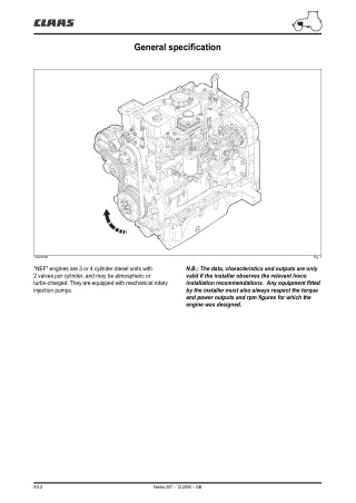
General specification 103vfm00 Fig. 1 "NEF" engines are 3 or 4 cylinder diesel units with 2 valves per cylinder, and may be atmospheric or turbo-charged. They are equipped with mechanical rotary injection pumps. N.B.: The data, characteristics and outputs are only valid if the installer observes the relevant Iveco installation recommendations. Any equipment fitted by the installer must also always respect the torque and power outputs and rpm figures for which the engine was designed. A3.2 Nectis 207 – 12.2005 – GB
Lubrication Operation The pressurised lubrication system uses a lobe oil pump located at the front of the block, driven by the splined ring attached to the crankshaft cone. Oil is pumped from the crankcase to the crankshaft, the camshaft and the cylinder head (oil cooler, turbocharger). Oil system layout (3-cylinder engine) 177 178 179 180 181 221vfm00 Fig. 3 Nomenclature 177 Turbocharger oil return line. 179 Oil cooler element. Oil pressure feed. 178 Oil filter. 180 Oil cooler. Oil gravity return route. 181 Oil pump. A3.8 Nectis 207 – 12.2005 – GB
Lubrication Oil system layout (4-cylinder engine) 182 183 184 185 186 221vfm01 Fig. 4 Nomenclature 182 Turbocharger oil return line. 184 Oil cooler element. Oil pressure feed. 183 Oil filter. 185 Oil cooler. Oil gravity return route. 186 Oil pump. A3.9 Nectis 207 – 12.2005 – GB
Cooling Operation The pressurised closed circuit engine cooling system has the following components: • Expansion tank. • Radiator, to dissipate the heat extracted from the engine by the coolant fluid. • Visco-static cooling fan to increase the radiator's heat dissipation capability, that also forms part of the engine's specific build. – An oil cooler to cool the lubricant oil – A centrifugal-type water pump located at the front of the engine block. – A thermostat that controls the circulation of the coolant fluid. Cooling (3-cylinder engine) A B 251vfm05 Fig. 5 Nomenclature A Radiator inlet. Coolant leaving the thermostat. Coolant entering the water pump. B Radiator outlet. Coolant recirculating within the engine. A3.10 Nectis 207 – 12.2005 – GB
Cooling Cooling system (4-cylinder engine) A B 251vfm06 Fig. 6 Nomenclature A Radiator inlet. Coolant leaving the thermostat. Coolant entering the water pump. B Radiator outlet. Coolant recirculating within the engine. A3.11 Nectis 207 – 12.2005 – GB
Turbocharger Operation Turbo-charged version of the engine 209 210 4 A 209 210 4 B 167vfm00 Fig. 7 Nomenclature 4 Exhaust. 210 Turbocharger. A 3 cylinder version. 209 Air filter. B 4 cylinder version. The air intake system consists of an air filter and an exhaust-driven compressor (turbocharger). Air from the compressor outlet is fed directly to the inlet manifold. A3.12 Nectis 207 – 12.2005 – GB
DIMENSIONS Dimensions - build clearances Type Atmospheric Turbo-charged Engine block and components of the crank drive mechanism (mm) Cylinder ø 1 Cylinder liner diameter 1 (machined) 104,000 – 104,024 X Piston Supplied replacement pistons: ø 1 Measured dimension (X) 52,4 55,9 X External diameter (ø 1) 103,755 – 103,773 103,730 – 103,748 ø 2 Gudgeon pin bore (ø 2) 38,010 – 38,016 38,010 – 38,016 Piston - Cylinder liner clearance 0,227 – 0,269 0,252 – 0,294 Piston diameter (ø 1) (repair size) Ø1 + 0,4 X Piston overtravel height (X) 0,28 – 0,52 Gudgeon pins (ø 3) 37,994 – 38,000 ø 3 Gudgeon pin clearance in piston 0,010 – 0,022 Piston ring grooves X1 2,705 – 2,735* 2,440 – 2,460 4,030 – 4,050 2,600 – 2,620 2,550 – 2,570 4,030 – 4,050 X1* X2 X3 X2 X3 Rings S1 S2 2,470 – 2,500 2,478 – 2,490 3,970 – 3,990 2,560 – 2,605 2,350 – 2,380 3,970 – 3,990 S1 S2 S3 S3 Ring clearance - groove 0,100 – 0,150 0,060 – 0,092 0,040 – 0,080 0,100 – 0,175 0,060 – 0,110 0,040 – 0,080 1 2 3 Rings + 0,4 * Measure across the 101 mm diameter. A3.13 Nectis 207 – 12.2005 – GB
DIMENSIONS Type Atmospheric Turbo-charged Engine block and crank assembly (mm) Piston ring gap in cylinder liner: X1 X2 0,30 – 0,40 0,60 – 0,80 0,30 – 0,55 0,25 – 0,55 0,30 – 0,55 0,30 – 0,55 X1 X2 X3 X3 Connecting rod Bush housing in small end (ø 1) 40,987 – 41,013 ø 1 Big-end bearing shell housing (ø 2) 72,987 – 73,013 ø 2 Small end bush dimensions ø 4 External (ø 4) Internal (ø 3) 40,987 – 41,013 38,019 – 38,033 ø 3 Replacement big-end bearing shells supplied (S) 1,955 – 1,968 S Gudgeon pin clearance - bush 0,019 – 0,039 Big-end bearing shells (repair size) 0,250 – 0,500 Crankshaft Main journals (ø 1) 82,990 – 83,010 ø 2 ø 1 Big-end journals (ø 2) 68,987 – 69,013 A3.14 Nectis 207 – 12.2005 – GB
DIMENSIONS Type Atmospheric Turbo-charged Engine block and crank assembly (mm) Crankshaft main bearing shells (S1) 2,456 – 2,464 S1 S2 Big-end bearing shells (S2) 1,955 – 1,968 Engine block Main bearing ø 3 N° 1 - 4 (ø 3) N° 2 - 3 (ø 3) 87,982 – 88,008 87,977 – 88,013 Set of bearing shells - main bearing N° 1 - 4 N° 2 - 3 0,064 – 0,095 0,059 – 0,100 Set of big-end bearing shells 0,033 – 0,041 Main bearing shells (repair size) Big-end bearing shells (repair size) + 0,250 ; + 0,500 Main bearing with thrust shoulder (X1) 37,475 – 37,550 X1 Main bearing with thrust shoulder (X2) 31,730 – 32,280 X2 X3 Thrust bearing shells (X3) 37,28 – 37,38 Crankshaft thrust bearing end float 0,095 – 0,270 A3.15 Nectis 207 – 12.2005 – GB
DIMENSIONS Type Atmospheric Turbo-charged Cylinder head - valvegear (mm) Valve Valve guide housings in cylinder head See detail under "valves" Valves: See detail under "valves" Clearance between valve stem and valve guide 0,039 – 0,079 Valve head recess below cylinder head face Intake (X) 0,336 – 1,072 X Exhaust (X) 0,104 – 0,840 A3.16 Nectis 207 – 12.2005 – GB
DIMENSIONS Type Atmospheric Turbo-charged Cylinder head - valvegear (mm) Valve spring height Spring unloaded: H 63,50 Spring under a load of: H 32,9 daN (H1) 49,02 H1 H2 64,1 daN (H2) 38,20 Injector Injector protrusion (X) Not adjustable X Camshaft Camshaft bearing housings: – Rear bearing diameter C (3-cylinder engine). – Rear bearing diameter C and front bearing diameter A (4-cylinder engine). 59,222 – 59,248 Camshaft bearing housings: – 2 intermediate bearings diameter B and front bearing diameter A (3-cylinder engine). – 3 intermediate bearings diameter B (4-cylinder engine). ø A ø B ø C 54,089 – 54,139 Camshaft bearings: ø 53,995 – 54,045 ø Bearing internal diameter (ø) 54,083 – 54,147 ø A3.17 Nectis 207 – 12.2005 – GB
DIMENSIONS Type Atmospheric Turbo-charged Cylinder head - valvegear (mm) Clearance between bearings and camshaft 0,038 – 0,152 Clearance between bearings and engine block 0,044 – 0,144 Effective valve lift: Exhaust (H) 11,02 H Intake (H) 10,74 Cam followers ø 1 Cam follower housing in block (ø 1) 16,000 – 16,030 Cam follower external diameter: 14 32 50 ø 2 ø 3 15,929 – 15,959 Ø2 ø 2 15,965 – 15,980 Ø3 Clearance between cam follower and housing 0,020 – 0,065 Rockers ø 1 Rocker shaft (ø 1) 18,963 – 18,975 Rockers (ø 2) 19,000 – 19,026 ø 2 Clearance between rockers and rocker shaft 0,025 – 0,063 Adjusting the valve rockers X Inlet valves x (mm) 0,25 ± 0,05 Exhaust valves x (mm) 0,50 ± 0,05 A3.18 Nectis 207 – 12.2005 – GB
DIMENSIONS Valves Inlet and exhaust valve dimensions (in mm). 7,960 7,980 7,960 7,980 Nomenclature 1 Exhaust valve. 2 Intake valve. 44,75 45,25 59,75 60,25 42,13 41,87 45,13 44,87 1 2 131vfm00 Fig. 8 Valve guide/seat dimensions 8,019 8,039 Nomenclature 3 Intake. 4 Exhaust. 3 4 131vfm09 Fig. 9 A3.19 Nectis 207 – 12.2005 – GB
DIMENSIONS Valve seat housing dimensions 3,460 3,200 50,5˚ 49,5˚ 50,5˚ 49,5˚ 3,470 ø 43,663 ø 43,637 ø 47,013 ø 46,987 1,980 1,580 1,810 1,550 ø 44,400 ø 50,000 ø 47,000 10,400 10,000 10,600˚ 10,200˚ 3 4 131vfm11 Fig. 10 Dimensions (mm) of valve seat inserts 47,089 47,063 43,739 43,713 45,5˚ 44,5˚ 60,5˚ 59,5˚ 6,516 6,440 6,804 6,728 ø 39,500 ø 42,500 4 3 131vfm12 Fig. 11 Nomenclature 3 Intake. 4 Exhaust. A3.20 Nectis 207 – 12.2005 – GB
Torque settings Front chassis / engine link A. 39 daN.m (4 M20 nuts). Engine/transmission link B. 8 daN.m + Frenetanch (242) (4 screws HM12x125-65). C. Locating pin. D. 8 daN.m + Frenetanch (242) (8 screws HM12x175-50). A A 103vfm02 Fig. 12 B B D D C C D D 103vfm03 Fig. 13 A3.21 Nectis 207 – 12.2005 – GB
Torque settings 9 16 20 23 19 26 18 8 14 1 4 15 34 22 3 25 6 33 7 35 17 5 24 28 32 11 27 2 13 30 31 10 12 29 21 101vfm00 Fig. 14 A3.22 Nectis 207 – 12.2005 – GB
Torque settings See Figure 14. 3 cylinders 4 cylinders Ref Attachment – Phase Torque in daN.m M8 x 1,25 x 10 1,5 ± 0,3 1 M8 x 1,25 x 50 2,4 ± 0,4 2 M8 x 1,25 x 35 M10 x 1,50 x 40/50 5 ± 0,5 3 M10 x 1,50 x 70/100 7 ± 0,5 (M8 x 1,25 x 20) x 2 4 2,4 ± 0,4 M8 x 1,25 5 M12 x 1,75 x 70 (2 phases) 5 ± 0,5 + 90° M12 x 1,75 x 140 (3 phases) 4 ± 0,5 + 90° + 90° 6 M12 x 1,75 x 180 (3 phases) 7 ± 0,5 + 90° + 90° M8 x 1,25 7 M8 x 1,25 x 25 8 M8 x 1,25 x 100 2,4 ± 0,4 9 M8 x 1,25 x 40 10 (M8 x 1,25 x 50) x 4 11 (M10 x 1,50 x 35) x 4 12 4,5 ± 0,5 (M10 x 1,50 x 25) x 2 13 (M12 x 1,15 x 75) x 6 First phase 5 ± 0,5 14 Second phase 90° ± 5° (M12 x 1,75 x 100) x 2 8,0 ± 1,0 (M12 x 1,75 x 78) x 14 15 (M16 x 1,50 x 80) x 3 20 ± 2 (M16 x 1,50 x 100) x 2 (M12 x 1,25 x 31) x 8 First phase 3,0 ± 0,5 16 Second phase 60° ± 5° Nut (rocker adjuster screw) 0,5 ± 0,1 17 M10 x 4 Nut 4,3 ± 0,6 18 Hydraulic coupling (M12 x 1,5) 3,5 ± 0,5 19 M8 x 3 Nut 2,4 ± 0,4 20 A3.23 Nectis 207 – 12.2005 – GB
Torque settings 3 cylinders 4 cylinders Ref Attachment – Phase Torque in daN.m M10 x 1,5 x 40 4,5 ± 0,5 21 M10 x 1,5 x 130 (M10 x 1,50 x 35) x 3 4,3 ± 0,5 22 M12 Screw First phase 5 ± 0,6 23 Second phase 8 ± 0,62 Third phase 90° ± 5° M8 Screw 2,4 ± 0,4 24 (M8 x 1,25 x 35) x 6 3,6 ± 0,4 25 M11 Screw First phase 6 ± 0,5 26 Second phase 60° ± 5° M8 x 1,25 x 25 2,4 ± 0,4 27 (M10 x 1,50) x 8 3,2 ± 0,3 28 (M8 x 1,25 x 65) x 3 29 2,4 ± 0,4 (M8 x 1,25 x 35) x 12 30 (M10 x 1,5 x 50) x 3 4,8 ± 0,5 31 Engine temperature sensor 2,5 ± 0,5 32 Temperature sensor 3 ± 0,2 33 Oil pressure sensor 3,5 ± 0,2 34 Drain plug 5 ± 0,5 35 A3.24 Nectis 207 – 12.2005 – GB
Checks/adjustments Compression 232 235 230 234 N.B.: before starting the test, make sure that the battery is fully charged and that the injector area is perfectly clean. – Start the engine and let it idle for 10 to 15 minutes to achieve an oil temperature of 40 °C. – Remove the injectors. – Fit the dummy injector n° 00 11 301120 (230) with compression tester n° 60 05 721169 (231) in place of the injector from n° 1 cylinder (fan end). – Disconect the engine shut down solenoid valve from the injector pump. – Connect the compression tester leads to the terminal on the starter solenoid (232) with the red clip (233) to the battery or the starter. – Turn the engine on the starter by pressing button (234) until the needle fully stabilises. – Move ring (235) to depressurise the unit until the needle returns to zero. – Advance the record sheet (236) by pressing button (237) on the side of the unit. – Repeat the test on the remaining cylinders. The compression should be between 18 and 22 bar. 236 231 233 237 103vfm12 Fig. 15 Engine oil pressure Remove the oil pressure sensor and fit pressure gauge n° 77 01 388 204 (9) to the block in its place (Fig. 16). Before checking the pressure, warm up the engine. Engine oil pressure should be between 0,7 and 3,5 bar. 9 103vfm06 Fig. 16 A3.25 Nectis 207 – 12.2005 – GB
Checks/adjustments Turbocharger pressure See chapter "A1". Pressure test point for the turbocharger without mixture limiter (Fig. 17). 103vfm13 Fig. 17 Pressure test point for the turbocharger with mixture limiter. 103vfm14 Fig. 18 A3.26 Nectis 207 – 12.2005 – GB
Thank you very much for your reading. Please Click Here. Then Get COMPLETE MANUAL. NO WAITING NOTE: If there is no response to click on the link above, please download the PDF document first and then click on it.
Checks/adjustments Valves Valve clearance Condition: Engine cold. – Turn the flywheel in the normal rotational sense until piston n° 1 (radiator end) is at top dead centre (TDC). To determine TDC position, see chapter A2 : "Remove/Refit". "Injector Pump". – Adjust clearance between rocker arms and valve stems. The setting is: – Inlet valves: 0,25 ± 0,05 mm. – Exhaust valves: 0,50 ± 0,05 mm. 13 11 12 131vfm04 Fig. 19 N.B.: To reduce the time taken to adjust the tappet/valve clearance, proceed as follows: Position cylinder n° 1 at the top of the compression stroke and adjust the valves marked with an asterisk in the following table. • 3-cylinder engine Cylinder N° 1 2 3 Intake * * — Exhaust * — * N.B.: Rotate the crankshaft 360° and adjust the valves marked with an asterisk in the table. Cylinder N° 1 2 3 Intake — — * Exhaust — * — A3.27 Nectis 207 – 12.2005 – GB
Checks/adjustments • 4-cylinder engine Valve lift (Engine cold) N.B.: Measuring valve lift enables any wear in the cam to be detected. Cylinder N° 1 2 3 4 1. Rotate the engine and position the valves as described the the "valve clearance" paragraph. 2. Reduce valve clearance to zero. 3. Place a dial gauge on the valve spring cup or on the valve cap and then set to "0". 4. Turn the engine until the dial gauge reaches a maximum value showing that the valve is fully open. Check the values against the specifications at the beginning of this chapter. 5. Measure valve lift as explained, then reset the tappet clearance. 6. If the specification figures are not met, remove the camshaft and check its condition. Intake * * — — Exhaust * — * — Note: Turn the crankshaft through 360° and adjust the valves marked with an asterisk in the table. Cylinder N° 1 2 3 4 Intake — — * * Exhaust — * — * A3.28 Nectis 207 – 12.2005 – GB
Checks/adjustments Dimensional check Checking and repairing the valves – Remove all carbon deposits using the recommended wire brush. – Check that there are no signs of seizure, cracking or burning on the valves. 131vfm06 Fig. 20 Using a micrometer gauge (14) measure the valve stem diameter (15). Refer to the chapter "Dimensional specifications". 15 14 131vfm07 Fig. 21 Clearance between stem and guide and valve centering These checks are carried out using a dial gauge (18) with magnetic stand positioned as shown. The play should be between 0,052 and 0,092 mm. Turn the valve (15) and check that the play does not exceed 0,03 mm. 18 15 131vfm08 Fig. 22 A3.29 Nectis 207 – 12.2005 – GB