Download
1 / 23
230 likes | 270 Views
service repair manual

E N D
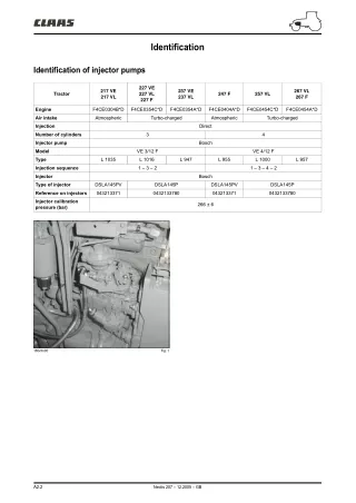
Identification Identification of injector pumps 227 VE 227 VL 227 F 217 VE 217 VL 237 VE 237 VL 267 VL 267 F Tractor 247 F 257 VL Engine F4CE0304B*D F4CE0354C*D F4CE0354A*D F4CE0404A*D F4CE0454C*D F4CE0454A*D Air intake Atmospheric Turbo-charged Atmospheric Turbo-charged Injection Direct Number of cylinders 3 4 Injector pump Bosch Model VE 3/12 F VE 4/12 F Type L 1035 L 1016 L 947 L 955 L 1000 L 957 Injection sequence 1 – 3 – 2 1 – 3 – 4 – 2 Injector Bosch Type of injector DSLA145PV DSLA145P DSLA145PV DSLA145P Reference on injectors 043213371 0432133780 043213371 0432133780 Injector calibration pressure (bar) 266 ± 6 160vfm00 Fig. 1 A2.2 Nectis 207 – 12.2005 – GB
Torque settings Torque settings 1 : 1,75 ± 0,25 daN.m 2 : 8,75 ± 0,25 daN.m 1 ± 0,2 daN.m 2,5 ± 0,3 daN.m 4,5 ± 0,5 daN.m 2,5 ± 0,5 daN.m 6 ± 0,5 daN.m 1 : 1,25 ± 0,25 daN.m 2 : 5,25 ± 0,25 daN.m 2,5 ± 0,5 daN.m 4,5 ± 0,5 daN.m 160vfm03 Fig. 2 A2.3 Nectis 207 – 12.2005 – GB
Description Fuel injector system with mechanical rotary pump General The fuel supply system consists of: – Fuel tank. – Fuel supply and tank return lines. – Fuel pre-filter. – Fuel pump. – Fuel filter. – Rotary injector pump. – Injector supply lines. – Injectors. 1 18 8 12 9 11 10 13 14 15 16 17 7 2 5 6 3 4 161vfm00 Fig. 3 A2.4 Nectis 207 – 12.2005 – GB
Description Nomenclature 1 Injector supply lines. 7 Pump shaft locking screw. 14 Connector for turbo pressure line in inlet manifold. 2 Injector. 8 Maximum speed adjustment screw. 15 Mixture limiter vent. 3 Cylinder n° 1 outlet. 9 Accelerator pedal. 16 Leakage return line. 4 Engine shutdown solenoid valve. 10 Fuel supply. 17 Full load flow control screw. 5 Injector pump. 11 Lever position adjustment screw. 18 Injector fuel return line. 6 Cold start advance correction device (electrovalve). 12 Idle adjustment screw. 13 Mixture limiter (according to model). A2.5 Nectis 207 – 12.2005 – GB
Description 20 21 19 22 5 161vfm05 Fig. 4 Nomenclature 5 Injector pump. 21 Line between fuel filter and injector pump. 19 Fuel filter. 22 Fuel pump. 20 Line between feed pump and filter. Operating principle Fuel is drawn from the fuel tank by the camshaft-driven fuel pump located on the engine block . The fuel then passes through the filter (19) to the transfer pump suction chamber inlet. The transfer pump (vane type) is located inside the injector pump and its role is to raise fuel pressure as a function of increases of engine rpm. The fuel then arrives at the valve that regulates the pressure within the injector pump. The distributor piston later raises this pressure and sends the fuel to the injectors via the outlet connector. Excess fuel is recovered and returned to the tank. A2.6 Nectis 207 – 12.2005 – GB
Description Injector pump E = Pump size. 4 = 4 cylinder engines (3 = 3 cylinder engines). 12 = Diameter of distributor piston (in mm). F = Mechanical regulator. 1 150 = Pump rpm. L = Direction of rotation. 955 = Pump model variant. The pinion of the rotary injector pump is driven by the camshaft pinion. Identification plate The identification plate is located on the pump body. Typical identification: VE4/12F1150L955. V = Rotary distributor piston. 23 37 24 36 25 26 27 35 34 28 29 30 31 33 32 161vfm04 Fig. 5 Nomenclature (injector pump longitudinal section) 23 Membrane. 28 Transfer pump. 33 Return connector. 24 Adjustment collar. 29 Drive shaft. 34 Hydraulic head. 25 Pushrod. 30 Cam plate. 35 Control platen. 26 Operating lever. 31 Advance mechanism. 36 Floating shaft. 27 Speed regulator. 32 Distributor piston. 37 Return spring. A2.7 Nectis 207 – 12.2005 – GB
Description Fuel pump The role of the pump is to deliver the fuel from the tank to the injector pump inlet. It is located on the engine block and is driven from the camshaft. 40 39 Nomenclature IN 22 Pump. 38 Fuel outlet (towards the filter). 39 Operating lever. OUT 40 Fuel inlet (from the tank). 41 Camshaft. 38 161vfm03 Fig. 6 22 39 41 161vfm02 Fig. 7 Line filter Filters: 300 microns. Refer to chapter "L" of the operator's manual for instructions on changing the line filter (57). 57 160vfm04 Fig. 8 A2.8 Nectis 207 – 12.2005 – GB
Description Fuel filter The filter is located near the injector/supply pump and its role is to collect impurities and to separate any water present in the fuel. At the base of the filter cartridge a water drain screw or a water detector is provided. Filters: 5 microns. 42 Nomenclature 19 Fuel filter. 42 Fuel filter bracket. 19 43 Water drain screw. 44 Water detector. 43 161vfm01 Fig. 9 42 19 44 161vfm06 Fig. 10 A2.9 Nectis 207 – 12.2005 – GB
Description Electrical components 47 48 5 4 6 46 51 19 50 44 53 161vfm07 Fig. 11 Nomenclature 4 Engine shutdown solenoid valve. 46 Engine temperature sensor. 50 Cold-start resistance. 5 Injector pump. 47 Starter. 51 Alternator. 6 Solenoid valve for cold start advance mechanism. 48 Water temperature sensor for the cold start advance mechanism. 53 Oil pressure transducer. 19 Fuel filter. 44 Water detector. A2.10 Nectis 207 – 12.2005 – GB
Description Engine temperature sensor The engine temperature sensor is mounted on the cylinder head, close to the thermostat housing, and records coolant temperature. Characteristics: System voltage:..............................................6 V to 12 V Resistances: at 80 °C........................................ 0,304 to 0,342 K.ohms at 20 °C........................................ 2,262 to 2,760 K.ohms at –10 °C.................................... 8,244 to 10,661 K.ohms C B A 46 A B C 161vfm09 Fig. 12 Water temperature sensor for the cold start advance mechanism This sensor is fitted to the cylinder head on the left side of the engine. Characteristics System voltage: 12 V. Operating threshold – 63 ± 3°C Contacts open with increasing temperature. – 53 ± 3°C Closure of contacts with decreasing temperature. 48 161vfm10 Fig. 13 A2.11 Nectis 207 – 12.2005 – GB
Description Solenoid valves on the injector pump Nomenclature 4 Engine shutdown solenoid valve. 6 Solenoid valve for cold start advance mechanism. 4 6 161vfm12 Fig. 14 Water detector A water detector (44) is fitted to the base of the fuel filter. For further information see chapter "Instrument panel, Characteristics". D B C A 12 V B 44 C A 161vfm13 Fig. 15 Oil pressure sensor This sensor (53) is fitted to the block on the left side of the engine. Characteristics System voltage: 12 V. Operating threshold – Contact closes. With decreasing pressure: 0,6 bar. – Contact opens. With rising pressure: 0,9 bar. b 0,9 0,6 161vfm14 Fig. 16 A2.12 Nectis 207 – 12.2005 – GB
Description Preheating element This is an electric element (50) located in the inlet manifold that is used to heat the air during pre-heating operations. The element is supplied from a remote controlled switch usually located near the engine. Characteristics System voltage: 12 V. Maximum possible air flow: 2 cm³/min (at a pressure of 138 kPa). 50 161vfm17 Fig. 17 A2.13 Nectis 207 – 12.2005 – GB
Description Pre-heating controller Description F = Fuse. R = Preheating element. T = Relay. GHC = Pre-heating controller. 30 +0 4 F F 6 GH 7 5 15 50 NTC 31 30 T GHC 10 8 FB N31 3 1 R 1,2 W 161vfm18 Fig. 18 Electrical diagram (output) Pin N° Description Output to "cold start" warning light. 1 Not used. 2 "feedback" signal input from the pre-heating element (FB). 3 Engine start signal input (D). 4 Start signal input (50). 5 Output to remote switch supplying preheating element (GH). 6 Supply positive (15). 7 Supply negative (31). 8 Not used. 9 Analogue temperature signal input (NTC). 10 This controller uses the remote switch to control the element as a function of engine coolant temperature. Characteristics System voltage: 12 V. Operating voltage: 7 V to 12 V. Operating temperature: – 40 °C to 85 °C. Maximum current in line "GH": 0,3 A. A2.14 Nectis 207 – 12.2005 – GB
Checks/Adjustments Accelerator control adjustment 105 102 101 106 B A 105 106 101 102 104 100 103 104 100 152vfm00 Fig. 19 A2.15 Nectis 207 – 12.2005 – GB
Checks/Adjustments – Attach the control cable to the accelerator lever on the injector pump (100). – Connect the control cable to the accelerator pedal (101). – Check in the cab that the manual control lever is set to minimum "A" (Fig. 19). – Adjust the cable at the pedal end to achieve a light tension then tighten the nuts (102). Ensure that the pump lever is tight against the idle speed adjustment screw (103). – Adjust the manual control cable (105) then tighten the nuts (106). – Correct adjustment should enable the engine throttle control (104) to return to the mechanical stop (103) when the lever or the pedal is at its minimum setting and enable an extension of the accelerator cable spring on the pump when the manual lever or the pedal is at its maximum setting. Injector pump Internal setting The pump must be removed and cylinder n° 1 must be at TDC on the compression stroke (refer to chapter "Removal/refitting", "Injector pump"). – Remove the central screw (101) on the distributor head. – Align the keyway slot in the shaft with the outlet for cylinder n° 1 item (B) for the 4 cylinder pump (5b) and item (A) for the 3 cylinder pump (5a). – Mount the pump shaft in a soft-faced vice. – Attach tool (89) reference n° 60 05 005 560 with the dial gauge (88) placing the shaft in contact with the head of the distributor piston. – Install the dial gauge at mid travel. – Turn the pump so that the shaft turns clockwise until the needle stops moving. – Set the dial gauge to zero. – Turn the pump so that the shaft turns anti-clockwise until the dial gauge reads 1 for turbo-charged engines and 1,15 for normally aspirated engines. 88 89 160vfm13 Fig. 20 101 86 B 5a 101 A 86 5b 160vfm14 Fig. 21 A2.16 Nectis 207 – 12.2005 – GB
Checks/Adjustments – Lock the shaft by tightening screw (86) then refit the pump (refer to chapter "Removal/refitting", "Injector pump"). – Check the pump installation (refer to paragraph "Checking the timing of the injector pump"). Checking the timing of the injector pump N° 1 cylinder must be at TDC on the compression stroke (refer to chapter "Removal/refitting", "Injector pump"). The pump must be attached to the engine block with the pump shaft free and the operating lever attachment nut tightened. – Remove the central screw on the distributor head. – Attach tool (89) reference n° 60 05 005 560 with the dial gauge (88) placing the shaft in contact with the head of the distributor piston (Fig. 22). – Install the dial gauge at mid travel. – Turn the engine flywheel against the normal operating direction until the dial gauge needle stops moving. – Set the dial gauge to zero. – Turn the engine flywheel in the normal operating direction to return to TDC (replace the flywheel locking pin). The dial gauge should show a reading of 1 for turbo-charged engines and 1,15 for normally aspirated engines. – If these values are not obtained, slacken the 3 pump attachment nuts and rotate it clockwise or anti-clockwise to obtain the desired reading. – Re-tighten the 3 pump attachment nuts. 89 88 160vfm07 Fig. 22 A2.17 Nectis 207 – 12.2005 – GB
Checks/Adjustments Injector Instructions for the removal of the injectors will be found in the chapter "Removal/refitting of injectors". Check the injector's pressure setting (see chapter "identification" for pressure values). Note: It is recommended to aim for the maximum value in the adjustment because after operating for some time the pressure drops slightly before stabilising. Repeat the adjustment in order to obtain a reliable result. Note: The injector nozzle must never be pointing towards the person performing the adjustment. The jet escaping from a port can pierce clothing and skin, and cause serious infections. The jet should be recovered in a transparent container. 160vfm05 Fig. 23 A2.18 Nectis 207 – 12.2005 – GB
Checks/Adjustments Supply pressure 100b 98 5 98 – Create a test installation as shown in figure n° 22 to check the fuel supply pressure. – Connect the ends of the lines (100a) to the filter outlet (19), (100b), to the injector pump inlet (5), (100c) and to the reference pressure gauge n° 60 05 005 521. – Start the engine. – Check the pressure (refer to chapter A1 "measurement and test points" for pressure values). – If the pressure is low, check the supply system (filter, strainer, hoses) and re-test. 19 97 101 100a Nomenclature 100c 5 Injector pump. 19 Fuel filter. 99 97 Pressure gauge. 160vfm08 Fig. 24 98 2 elbow connectors reference n° 00 11 306 150. 99 6 hose clamps. 100 Fuel pipe (internal diameter 9,5 mm). 101 "T" piece reference n° 77 00 067 854. A2.19 Nectis 207 – 12.2005 – GB
Removal/refitting Fuel filter 21 42 Removal of the fuel filter bracket – Place a container under the fuel filter and unscrew the condensation drain covers under the filter. Drain out all the fuel present. – Unscrew fully the valve and remove the fuel filter (19). – Disconnect the fuel lines (20), (21) from the feed pump to the filter bracket and from the latter to the injector pump. – Remove the fuel filter bracket (42). To disconnect the fuel lines (20), (21) (Fig. 25), press down on the fastener (54) as shown in figure (B). After disconncting the lines, withdraw the fastener (54) to its locked position (Fig. A). 20 19 Refitting the fuel filter Proceed in reverse order to the removal operations. 161vfm19 Fig. 25 A B N.B.: Before refitting the fuel filter (19), it must be refilled with fuel to facilitate the bleeding of the fuel feed system. 54 54 161vfm20 Fig. 26 Injection system Injection system bleeding Refer to the user manual. A2.20 Nectis 207 – 12.2005 – GB
Thank you very much for your reading. Please Click Here. Then Get COMPLETE MANUAL. NO WAITING NOTE: If there is no response to click on the link above, please download the PDF document first and then click on it.
Removal/refitting Injector pump Finding top dead centre (TDC) – Remove the starter motor. – Fit the flywheel rotation tool (90) reference n° 77 01 388 169 (Fig. 27). 90 91 160vfm09 Fig. 27 1st method (Fig. 27) – Turn the flywheel carefully in the normal rotational sense to take up the play in the gear train. – Turn the flywheel until the 8mm pin ø8 (91) engages in the socket on the flywheel provided for this purpose. – Check that cylinder n° 1 is at TDC on the compression stroke, in other words the inlet and exhaust valves are both fully closed and not partially lifted. 2nd method (Fig. 28) – Remove the first injector, fit tool n° 00 11 308 920 (81) with a dial gauge (82) and remove the rocker cover (83). – Use the flywheel rotation tool (90) n° 77 01 388 169 to turn the crankshaft until n° 1 cylinder is at TDC. TDC on the compression stroke for n° 1 cylinder is obtained when the dial gauge needle is at its maximum value and the inlet and exhaust valves are both closed and not partially lifted. 82 83 81 161vfm34 Fig. 28 A2.21 Nectis 207 – 12.2005 – GB
Removal/refitting Removal of injector pump on 3-cylinder engines – Disconnect the elecrical harness (58) from the engine shut down and cold start solenoid valves. – Release the clamp from the fuel scavenge pipe (18) return to the injector pump. – Release the clamp from the fuel supply (10) and scavenge (59) pipes. – Remove the turbo pressure line (55). – Remove the roll bar (depending on equipment fit). – Remove the feed pump and if necessary the oil pressure sensor. 18 55 6 10 58 59 160vfm06 Fig. 29 A2.22 Nectis 207 – 12.2005 – GB
Removal/refitting 62 1a 61 18a 63 2a 5a A 60 64 161vfm25 Fig. 30 Nomenclature 1a Injection pipes. 61 Attachment screw for small rear bracket (on the inlet manifold plate). 64 Attachment screw for the small bracket near the injector pump. 2a Injector. 62 Bracket attachment screw. A Cylinder n° 1 outlet. 5a Injector pump. 63 Attachment screw for small front bracket (on the inlet manifold plate). 18a Fuel return line to the injector pump. 60 Injector pump outlet connector. – Unscrew the injector connectors (60). – Unscrew the screws that retain the tube attachment brackets (63), (64), (61), (62) then remove the tubes (1a). – Fit blanks to the ends of the tubes. A2.23 Nectis 207 – 12.2005 – GB