Download
1 / 25
250 likes | 259 Views
service repair manual

E N D
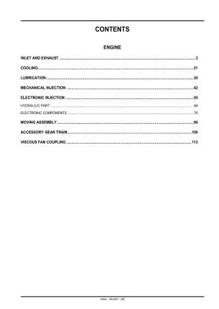
CONTENTS ENGINE INLET AND EXHAUST .......................................................................................................................................3 COOLING..........................................................................................................................................................21 LUBRICATION..................................................................................................................................................30 MECHANICAL INJECTION ..............................................................................................................................42 ELECTRONIC INJECTION...............................................................................................................................55 HYDRAULIC PART ............................................................................................................................................................66 ELECTRONIC COMPONENTS..........................................................................................................................................76 MOVING ASSEMBLY.......................................................................................................................................98 ACCESSORY GEAR TRAIN...........................................................................................................................108 VISCOUS FAN COUPLING............................................................................................................................113 Celtis – 09.2007 – GB
First line (1): Serial number (13 characters) Tractor prior to May 2005 CD Engine built at the Saran factory 4 O45 4,5 litres capacity D Normally aspirated engine T Turbo-charged engine Tractor after May 2005 CD Engine built at the Saran factory 4 O45 4,5 litres capacity B Uncertified engine C Tier 1 engine (will be followed by the letter E then F when the counter reaches 999999) G Tier 2 engine (will be followed by the letter J then K when the counter reaches 999999) 123456 Number within the series 4 cylinders 4 cylinders H Turbo-charged engine with intercooler 5 7 Tier 1 engine Tier 2 engine 12345 Number within the series Second line (2): Engine type 4 045 T RT 52 See above RENAULT Agriculture application Application issue Celtis – 09.2007 – GB A.2
Inlet and exhaust Technical description Cylinder head H 131msm00 This can be identified by: The cross-flow design. Inlet ducts have been redesigned to increase turbulence in the cylinders SWIRL, and hence improve air/fuel mixing. A cast letter (H) in the inlet port identifies the model of cylinder head. The cylinder head now incorporates a housing for the direct mounting of the thermostat. The cylinder head gasket is specific. It has a compressed graphite film on both surfaces. Celtis – 09.2007 – GB A.3
Valves A – Collets. B – Valve rotator. C – Spring. D – Umbrella seal. D C B A 131hsm10 The valve guides are machined directly in the cylinder head. A helicoidal open groove improves lubrication between the guide and valve. An "umbrella" type seal (D) allows the passage of a controlled quantity of oil to provide lubrication for the valve stem. Each valve is fitted with a rotator (B) ensuring a rotation of 2° each time the valve operates. The contact surface between the valve head and the seat insert is thus always clean. Celtis – 09.2007 – GB A.4
Schematic diagram Air circulation I J H G t° K t° F E M C B D A L 141msm00 Celtis – 09.2007 – GB A.5
A – Filter. B – Filter blockage thermal switch. C – Pneumatic compressor. D – Turbocharger. E – Intercooler. F – Turbocharger pressure sensor (according to model). G – Air temperature thermistance. H – Pre-heat flange. I – Pre-heat relay. J – Instrument panel. K – Intake/exhaust. L – Particulate rebreathing. M – Check valve. Celtis – 09.2007 – GB A.6
Technical specifications Pre-heating – Mechanical injection: Pre-heating is activated by holding the key at position III on the master switch. The pre-heat warning light illuminates. Maximum pre-heat duration is 20 seconds (Instrument panel time delay). A 1 200 W heater is fitted between the manifold and the intake pipe. – Electronic injection: Both the pre-heating and the illumination of the instrument panel warning light are controlled by the engine ECU. Particulate rebreathing Particulate rebreathing is achieved by a duct subject to a venturi effect between the exhaust pipe and the air filter. DIMENSIONS Cylinder head A B 130hsm00 A. 104,87 mm 105,13 mm 0,73 mm 104,11 mm Minimum acceptable cylinder head thickness Maximum acceptable cylinder head thickness Maximum acceptable cylinder head rework Minimum cylinder head thickness after rework B. 0,08 mm Cylinder head flatness over entire length Celtis – 09.2007 – GB A.7
Valves G C H D J F I E 131hsm00 INTAKE EXHAUST C. G. 7,864 mm 7,848 mm Minimum diameter of valve stem Minimum diameter of valve stem 7,884 mm 7,874 mm Maximum diameter of valve stem Maximum diameter of valve stem D. H. 0,05 mm 0,05 mm Minimum clearance between stem and guide Minimum clearance between stem and guide 0,10 mm 0,10 mm Maximum clearance between stem and guide Maximum clearance between stem and guide 0,15 mm 0,15 mm Wear limit Wear limit E. I. 0,61 mm 1,22 mm Minimum valve withdrawal Minimum valve withdrawal 1,11 mm 1,72 mm Maximum valve withdrawal Maximum valve withdrawal 1,63 mm 2,26 mm Wear limit Wear limit F. J. 46,47 mm 42,37 mm Minimum diameter of valve head Minimum diameter of valve head 46,73 mm 42,63 mm Minimum diameter of valve head Minimum diameter of valve head Celtis – 09.2007 – GB A.8
Rocker shaft A 313hsm01 Adm. – Intake Ech. – Exhaust LU. – Wear limit Celtis – 09.2007 – GB A.9
A. 54 mm 46 mm 34,5 mm Uncompressed length Length compressed to 24 daN Length compressed to 68 daN Celtis – 09.2007 – GB A.10
Turbocharger CZ 0,83 bar Type of turbocharger Normal turbocharger pressure at full load nominal speed 165hsm00 Celtis – 09.2007 – GB A.11
Check of valve lift Note: Measuring valve lift enables any wear in the cam to be detected. – Fit the flywheel rotating tool 60 05 005 501 in (A). – Using tool No. 60 05 005 501 turn the flywheel in its normal direction (clockwise when viewed from the water pump) until piston No. (1) (at the front) is at top dead centre (TDC) of its compression stroke. – Fit the lock pin n° 60 05 005 576 in (B). – Eliminate the clearance between the rocker arm and the valve stems on exhaust valves n° 1 - 3 and inlet valves n° 1 - 2. – Place a dial gauge on the valve spring cup or on the valve cap and then set to 0. – Remove the lock pin, turn the engine, and observe the dial gauge up to the point of maximum valve opening. A B 131msm13 – Measure valve lift and compare it with the values mentioned in "Dimensional specifications". – Turn the engine by a full revolution 360°. Lock the engine at TDC on the compression stroke for piston (4). – Eliminate the clearance between the rocker arm and the valve stems on exhaust valves n° 2 - 4 and inlet valves n° 3 - 4. – If the specifications are not followed, remove and check the camshaft condition. – Place a dial gauge on the valve spring cup or on the valve cap and then set to 0. – Measure valve lift and compare it with the values mentioned in "Dimensional specifications".. – If the lift of one or several valves is not within specifications, remove and inspect the entire valve set and camshaft. 131msm02 Celtis – 09.2007 – GB A.12
Head gasket failure - investigation procedure Preliminary checks Three types of seal failures can occur: – Combustion gas faulty sealing. – Cooling system faulty sealing. – Lubrication system faulty sealing. A – Combustion gas sealing surface B – Oil sealing surfaces C – Coolant sealing surfaces A B C 135msm03 Celtis – 09.2007 – GB A.13
Visual inspection to be carried out before intervention on the cylinder head gasket: – Presence of oil or coolant on the seal face or adjacent surfaces. – Seal displaced in respect of its normal position. – Discoloration or presence of soot caused by a combustion gas leak – Leak on the radiators (oil and water), the tank, overflow, or pipe hoses. – Coolant leaking at the water pump bleed hole. – Presence of coolant on the cylinder head gasket. – Presence of coolant in the crankcase. – Insufficient coolant level. – High oil level. – Presence of cooling liquid in the engine breather (A). A 131hsm16 Pressurized test of the cooling system: Before the test, warm the engine. Let the engine cool down, and remove the radiator cap cautiously. If no leak is visible, but if pressure drops, there may be an internal coolant leak or an internal leak in the seal between the block and the cylinder head. 0,7 bar 131hsm15 Celtis – 09.2007 – GB A.14
Combustion gas sealing Symptoms: – Loss of power. – Irregular engine running. – White smoke at the exhaust pipe. – Air bubbles in the water radiator or the overflow tank. – Cooling fluid leak from overflow pipe. – Engine overheating. – Loss of heating in driver's cab. – Coolant in a cylinder. – Coolant in the crankcase oil. – Insufficient coolant level. Possible causes: – Cracks, folds in the seal surfaces. – Damages, punctures in the elastomer ribs. – Cracks, folds in the seal surfaces. O-ring damaged or missing at the push rod oil orifice. – Excessive liner protrusion. – Excessive difference in liner protrusion between the cylinders. – Insufficient tightening torque. – Distorted, damaged, or irregular engine block surface. – Distorted, damaged, or irregular cylinder head surface. – Oil or fluid overheating. IMPORTANT: Oil cooling failures can cause the presence of oil in the cooling fluid. Celtis – 09.2007 – GB A.15
Coolant sealing Symptoms: – Coolant leaking through the cylinder head gasket. – Coolant in the oil pan. – Insufficient level in the tank. – High oil level. – Coolant leaking through the crankcase breather. Possible causes: – Excessive liner protrusion. – Excessive difference in liner protrusion between the cylinders. – Insufficient tightening torque. – Deformed, damaged, or irregular engine block surface. – Deformed, damaged or irregular cylinder head surface. – Oil or coolant temperature too high. – Cylinder head gasket surface deformed or cracked. – Elastomer parts of cylinder head gasket damaged or cracked. Lubrication system sealing Symptoms: – Oil leaking through the cylinder head gasket. – Oil in the coolant. – Insufficient oil level in the crankcase. – Insufficient rocker lubrication (abnormal noises). Possible causes: – Excessive liner protrusion. – Excessive difference in liner protrusion between the cylinders. – Insufficient tightening torque. – Deformed, damaged, or irregular engine block surface. – Deformed, damaged or irregular cylinder head surface. – Oil or coolant temperature too high. – Cylinder head gasket surface deformed or cracked. – Elastomer parts of cylinder head gasket damaged or cracked. – O-rings damaged in the oil passages to the rockers. IMPORTANT: Oil cooling failures can cause the presence of oil in the cooling fluid. Celtis – 09.2007 – GB A.16
Checking the turbocharger pressure – Remove the plug (1) or (2). – Install the pressure gauge n° 60 05 005 521 – Before checking, run the engine. 1 2 101msm50 – Observe the pressure gauge. The lift pressure should be, when the engine is running at full load and reaches nominal speed: 4045 TRT 77 engine 4045 TRT 78 engine 4045 TRT 72 engine 0,52 bar 0,60 bar 0,76 bar If the pressure is too low, check the following points: – Air filter clogging. – Leak at the intake circuit, between the turbocharger and cylinder head. – Faulty turbocharger. Celtis – 09.2007 – GB A.17
Turbo checks Radial shaft play – Fit on the turbocharger a comparator fitted onto a support with a graduated extension, and fit the graduated extension on the shaft of the compressor, by passing it through the lubrication orifice. – Push and pull alternately the compressor shaft. – With equal pressure applied to both ends of the shaft, the clearance should not exceed the values indicated in the chapter "Dimensional specifications". 251msm27 Axial shaft play – Using a comparator contacting the shaft, measure axial clearance. – Move the shaft axially by hand in both directions and compare the value read with the values specified in the chapter "Dimensional specifications". 251msm18 Celtis – 09.2007 – GB A.18
Reconditioning the turbocharger IMPORTANT: It is difficult to recondition a turbocharger without the tools and training required: do not totally disassemble a turbocharger. If a turbo is found to be faulty when checked, replace it. Note: When refitting, use the recommended torque settings. IMPORTANT: When refitting, oil the turbo bearings to ensure lubrication on engine start-up. 167msm00 Celtis – 09.2007 – GB A.19
Cooling Technical description Cooling system 251msm00 Celtis – 09.2007 – GB A.20
Thank you very much for your reading. Please Click Here. Then Get COMPLETE MANUAL. NO WAITING NOTE: If there is no response to click on the link above, please download the PDF document first and then click on it.
A – Water pump. B – Coolant passage adaptor. C – Oil cooler drain plug. D – Oil cooler plates. E – Cooling fluid passage. F – Cooling fluid envelope. G – Passages in the upper part of the block. H – Passages. I – Thermostat. J – Water manifold/thermostat housing. L – Bypass circuit. M – Towards the radiator upper tank. N – Drain plug. O – Water pump suction side. P – High temperature cooling fluid. Q – Low temperature cooling fluid. R – Cabin heater valve. S – Cabin heater radiator. T – Engine management thermistance. U – Instrument panel thermistance (depending on the model). V – Heat exchanger. W – Expansion bottle. Celtis – 09.2007 – GB A.21
Schematic diagram Cooling system O A D J H E U t˚ G F L t˚ R T I S t˚ M W V X 221msm05 x – Depending on installation. Celtis – 09.2007 – GB A.22
Technical specifications Thermostat The thermostat sits within the cylinder head under the water housing. Part of the coolant flow is diverted to the water pump via a steel tube. The temperature is regulated between 82 and 95°C. A – Coolant temperature probe A 251msm01 During filling, bleed the system by loosening the temperature probe or the plug (depending on installation) at position (A). A 251msm02 Celtis – 09.2007 – GB A.23
Water pump The water pump is fitted under the accessory gear train cover and uses the cavity in the cover as the pump body. 251msm03 Degraded modes Coolant temperature too high First check coolant quality and level. Check for leaks from external engine system components. 1. FAULTY Go to 2. GOOD Go to 4. YES Check the cylinder head and the cylinder head gasket. See: Head gasket failure - investigation procedure. NO Go to 3. YES Go to 4. NO Problem solved. 2. CHECK FOR THE PRESENCE OF OIL IN THE COOLANT HEADER TANK. 3. DRAIN THE COOLANT. – Refill to the correct level. Does the problem remain ? 4. CHECK THE RADIATOR: – Dirt ; – Leaks ; – Blockage. Repair or replace the defective components. Does the problem remain ? YES Go to 5. NO Problem solved. Celtis – 09.2007 – GB A.24