Download

1 / 21
210 likes | 224 Views
service repair manual

E N D
SM 622 CDP 100/164 Service Manual
Contents of this Manual Group Index Group SA .......................................................................................... Group PS ............................................................................................ Group 00 ................................................................................................. Group 01 .............................................................................................. Group 02 .................................................................................................... Group 03 ..................................................................................... Group 06 .................................................................................................. Group 12 .............................................................................................. Group 13 ................................................................................................... Group 14 ............................................................................................ Group 20 ...................................................................................................... Group 21 ............................................................................................... Group 22 ............................................................................................ Group 23 .................................................................................... Group 24 .................................................................................. Group 25 ............................................................................. Group 26 ........................................................................ Group 29 ................................................................ Group 30 ............................................................. Group 32 ................................................................................................. Group 34 ...................................................................... Group 38 ..................................................... Group 39 ................................................................ Group 40 ................................................................................................. Safe Maintenance Periodic Service Diesel Engine Cooling System Fuel System Air Induction System Transmission Ignition System EGS Control Electrical System Drive Axle Universal Joint Wheels and Tires Parking Brake System Wet-disc Brake System Steering Column and Gear Steer Axle and Steer Cylinder Hydraulic Pump, Sump and Filters Hydraulic Control Valve/Lift Circuit Tilt Cylinders Uprights, Carriages, and Forks Counterweights, Sheet Metal and Chassis Decal Replacement and Placement Specifications Alphabetical Index Air Induction System.. ......................... Group 03 Alternator.. ........................................... Brake System.. ..................................... Cooling System ................................... Counterweight ..................................... Decals .................................................. Drive Axle ........................................... EGS ...................................................... Electrical System ................................. Engine (Diesel) .................................... Fuel System ......................................... Hydraulic Control Valve ..................... Group 30 Instrument Panel .................................. Lift Cylinder ........................................ Oil Change ........................................... Radiator ............................................... Safety .................................................. Sheet Metal & Chassis.. ....................... Group 38 Shop Supplies ...................................... Specifications ...................................... Starter .................................................. Steer Axle ............................................ Steering Column and Gear .................. Group 25 Tilt Cylinders ....................................... Transmission.. ...................................... Tune-up.. .............................................. Universal Joint ..................................... Uprights, Carriages, Forks ................... Group 34 Water Pump ................................... Wheels and Tires ................................. Group 01 Group SA Group 14 Group 23 Group 01 Group 38 Group 39 Group 20 Group 13 Group 14 Group 00 Group 02 Group 40 Group 40 Group 14 Group 26 Group 32 Group 06 Group 00 Group 21 Group 13 Group 34 Group 00 Group 01, 00 Group 22 SM 622, Nov ‘98 Contents-l
Major Component Location Use this illustration to help locate components included in the PM procedures. r 2 Engine Cooling Fuel Exhaust Transmission Drive Axle-Differential Wheels and Tires Upright and Carriage Frame and Counterweight Sheet Metal Cab Overhead Structure Prop Shaft 1. 2. 3. 4. 5. 6. 7. 6. 9. 10. 11. 12. SM 622, Nov ‘98 Contents-2
GROUP PS PERIODIC SERVICE Maintenance Schedules ........................................................... Section 1 The Planned Maintenance Program ...................................... Section 2 The PM Inspection Form ........................................................ Section 3 SM 622, Nov ‘98 Periodic Service
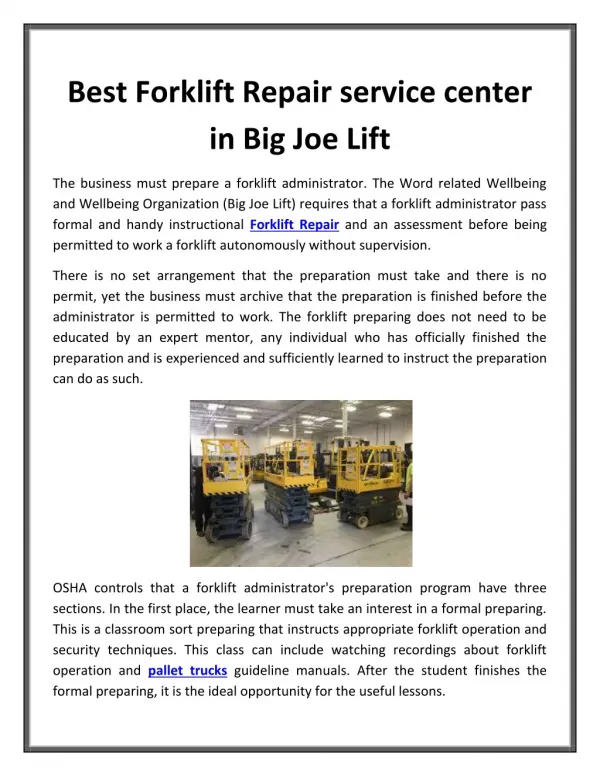
Group PS, Periodic Service Section 1. INTRODUCTION Proper maintenance is to be always ready for use. These preventative guide which should be followed when servicing your Clark truck. A lubrication guide and recommended nance program is included in this section and for further information regarding adjustment procedures, specifications, etc., please refer to the index in the front of this manual. c) Use in areas of frequent temperature loading bays handling plants, or making frequent trips from a building into the open air and back again. changes such as and care are essential if your Clark truck frozen goods, at refrigeration maintenance procedures provide a basic IMPORTANT preventative mainte- Your Clark truck is designed for work in all of the above conditions, however if your particular appli- cation should fall into Class 2,3 or 4 then appropri- ate changes to service frequencies must be made to all maintenance procedures. IMPORTANT Your Clark dealer has both the facilities, parts, and adequately trained personnel enabling them to carry out all necessary service procedures, including com- plete inspections, maintenance grams, all aimed at ensuring your Clark Lift truck will perform safety and efficiently and most impor- tantly, maximizing its availability day work schedules. LUBRICATION Greasing should be carried out every 250 hours, or after any washing. and lubrication pro- SAFETY . PRECAUTIONS When lifting parts or assemblies, slings, chains or cables are correctly fastened and that the load being lifted is balanced. Make sure that the crane, cables and chains have the capacity to support the weight of the load. Do not lift heavy parts by hand. Use a lifting mechanism. Wear safety glasses. Disconnect the battery ground cable. Always use correct blocks to prevent the unit from rolling or falling. Keep the unit and working area clean and in order. Use the correct tools for the job. Keep the tools clean and in good condition. Always use original Clark parts when making repairs. Make sure that all nuts, bolts, snap rings and other fastening devices are removed before using force to remove parts. Always fasten a DO NOT OPERATE sign to the controls of the unit when making repairs or if the unit needs repairs. Make sure you follow the DANGER WARNING CAUTION notes in the instructions. Diesel is a flammable fuel. Make sure that you follow the necessary safety precautions when working on the fuel system. Batteries generate flammable charged. Keep fire and sparks away from the area. Make sure the area has ventilation. DURING MAINTENANCE make sure that all for your day to RECOMMENDED Particular attention should be paid to the conditions which your CDP 100/164 forklift truck is used as those conditions play a significant role in determining how long the interval between each maintenance MAINTENANCE PROCEDURE under . . . . task should be. It is quite clear that a truck used in sandy, dusty, dirty locations will require more frequent maintenance being used in a clean warehouse situation. than one . . . . . The maintenance this book apply for use under normal operating conditions. schedules and recommendations made in The following conditions.. classifies the different types of operating . Class 1 - Normal conditions of use Basically transfer and loading of goods and materials for eight hours per day in buildings or in the open air. . and . Class 2 - Longer hours of use or continuous 3 shift operation. when handling fuel and . gas when they are being Class 3 & 4 - Extreme conditions a) Use in sandy or dusty places, such as cement works, steel mills, saw mills, flour mills, brick factories, or rock breaking applications. b) Use in areas of high temperature including steel works, foundries, etc. Psi-1 -1 SM 622, Nov ‘98
Grout PS. Periodic Service SAFETY PRECAUTIONS ING & BLOCKING Lifting or jacking any large piece of equipment, such as your Clark fork truck, presents obvious hazards. It must be with great care and forethought. Consult the truck weight tabula- tions in the specifications sections of this manual to ensure that your lifting equipment is of adequate capacity. DURING LIFTING, JACK- Engine (at operating temperature) ? Check engine oil level ? Check fan belt tension ? Start engine and check for obvious leaks in fuel system, lubricating oil system and cooling system stem. ? Check that all external screws, nuts, and securing parts are firm. Transmission (at operating temperature 83’ - 94 “C) oil filter The correct way to lift the front of the CDP100064 rigging a chain pull lift or hoist to the upright through the lift eyes provided. Chock the steer wheels before lifting. Place wheel stands under the drive tires or solid blocking under the base of the upright rails. is by ? Change transmission- ? Take sample of transmission oil (if on S.O.S. system) ? Check all screws, nuts and securing parts are tight and have a firm seat. General . . Check that all screws, nuts and securing parts are firm and pay particular attention to the wheel and upright studs and nuts. (See Critical Torque areas on following page). Crease all grease points (steer axle, upright, etc.) A WARNING The upright should be fully down before lifting. On uprights with negative drop such as Marina trucks, clamp or chain the rails together so they cannot move if at all possible, remove the forks before lifting by the upright. This work should be carried out by a qualified IMPORTANT Clark service mechanic. The rear of the truck may be lifted by the counterweight. Chock the drive wheels before lifting and be sure lifting equipment is of adequate capacity. b) Any preventative grammed planning of all service work and also on correct, up to date records being held, enabling systematic scheduling and tracking of maintenance vary from systems which are of a manual nature or computer assisted. Maintenance Records maintenance system relies on the pro- costs per unit. This does not A WARNING Check to see if the counterweight and property torqued before lifting. Never at- tempt to lift the rear of the truck with another fork truck. bolt is in place To ensure that the daily inspections and periodical preventa- tive maintenance services are properly performed, werecom- mend the use of inspection provide a guide for the person carrying out such inspections and services, but serve as a record in keeping track of maintenance requirements for each vehicle. Moreover, such records eventually assist you in determining ule downtime for major component disruptive effects of unscheduled dealer is always able to provide assistance maintenance systems and also in keeping maintenance records on your behalf. forms. Such forms not only 3. Place wheel stands under the steer tires or put solid blocking under the truck frame. when to sched- overhaul without the downtime. in setting up A WARNING Your Clark Take care to place block under the frame back far enough from the truck center of gravity so that it is stably supported. A typical maintenance This should be used as a guide to the minimum requirements and should be adapted to suit local conditions and operational experience. schedule is provided in this manual. INITIAL SERVICING & MAINTENANCE RECORDS a) An initial service should be carried out after your Clark forklift truck has been in operation for fifty hours. Initial Service VISUAL CHECKS Check that all capacity, safety and warning plates or decals are attached and legible. Check, before and after starting engine, for any sign of external leakage; fuel, engine coolant, transmission fluid, etc. Check for hydraulic oil leaks and loose fitting. In this service, the following (Check the Preventative work must be carried out: Maintenance schedule) PS-l-2 SM 622, Nov ‘98
Group PS, Periodic Service A WARNING FUEL SAFETY PRACTICES Take care when filling, not to allow any fuel to spill or flow into the engine compartment. Fuel in the engine compartment is afire hazard and should be completely removed immeadiately. Do not use bare hands to check. Oil may be hot or under pressure. Be sure that the devices safety devices are in place, undam- aged and attached securely. For example: seat belt, horn, load safety rail, beacon etc. Then check all of the critical components that handle or carry the load. Inspect the upright and lift chains. Check for obvious wear and maintenance problems such as damaged or missing parts, leaks, slack or broken chains, bent parts, etc. Use clean, properly marked fuel cans. Carefully inspect the load forks for cracks, breaks, bending, twists and wear. Be surd that the forks are correctly Installed and looked In their proper position. Inspect the wheels and lyres for safe mounting, wear condi- tion and correct inflation pressure. Function Checks Test warning devices, horn, lights and other safety equipment and accessories. Start the engine and be sure all controls and systems are functioning correctly. Check the hour meter for operation. Operate the service and parking brakes, all hy- draulic controls: lift, tilt and auxiliary functions. accelerator, directional control and steering system. Be sure all controls operate freely and return to neutral properly. Operate the lift mechanism and auxiliary functions, accelerator, directional control and steering system. freely and return to neutral properly. Operate the lift mecha- nism and auxiliary function (if Installed). Clean up spills. Be sure all controls operate Standard Shut Down Procedure When parking and leaving truck unattended, lift mechanism shall be fully lowered, controls placed in neutral, engine shut off, brakes set and key removed. is parked on an incline or has the possibility of moving. Chock the wheels if truck Make a record on the Drivers Daily Checklist of all the operating and truck problems that you find. checklist to be sure it has been completed and turn It In to the person responsible for lift truck maintenance. unusual noises or problems are investigated Review the Be sure any immediately. Do not operate a lift truck that has a maintenance problem, or is not safe to operate. Remove the key from the-ignition Service” tag on the truck. switch and put an “Out of If all of the “Before Operation” checks were normal or satisfactory, the truck can be operated. PS-1-3 SM 622, Nov ‘98
SnmY Workshop instructions WHEEL HUBS Removal: - Lift axle up and support it onto axle stands. Take wheel off. - Remove drain plugs (arrow in picture 1) and drain oil from the planetary gears to suitable container. Picture 3. Planetary carrier removed - Pull the half shaft out from axle casing. Take care of the protection plate, which is under the sun gear on the axle threads. - Remove lock screws from the bearing adjustment nut and straighten lock plate tab in the groove of the nut. Undo the nut and take care of it and the lock plate under it. See picture No. 4. Picture 1 - Unscrew hub cover retaining screws (5 PCS) and remove the cover. - Remove locking ring (arrow) in picture No. 2. Now the planetary carrier can be pulled out. Picture 4 - Now it is possible to pull the ring wheel with the hub out from the axle tube. Outer hub bearing will follow with the ring wheel hub. To make removal easier, do support the wheel hub a little. Picture 2 Oy Sisu-Auto Ab 2
Workshop instructions -After removal of the planetary ring wheel and its hub you can pull the wheel hub out. The inner wheel hub bearing and the hub seal will follow. It is possible to remove brake drums separately if necessary, for example to make wheel hub assembly lift easier. Picture 5. Removal of the wheel hub. Brake drum is already removed Dismantling: Remove first the hub seal and after this you can take the inner wheel hub bearing out. Remove bearing outer races from hub by using soft drift, if bearing replacement is required. Dismantle the planetary carrier by pressing the pins of the planetary gears out from inside by using a workshop press. After pin removal are the planetary gears with bearing needles, trust washers and spacers all loose and do this carefully and take care of all parts. Take care of the pin locking balls too. (See picture 6) Picture 6. Planetary carrier unit in parts 3
Bnzm Workshop instructions Assembly: Inspect the wheel hubs carefully before the assembly. The wheel hub seal should be replaced always. Bearings have to be inspected carefully and replaced if any defects, as scratches, wear spots or discolouring. Check also that bearing outer races are tight in their seat. If races are loose in the hub, the hub has to be replaced. Inspect condition of the planetary ring wheel and its fixing into the hub. If any defects are found in the ring wheel it has to be replaced. Before removal of the ring wheel you have remove the retaining ring (9 in picture 8) Install bearing races by a workshop press to assure their correct installation into their seats. When the races are installed, place inside bearing onto the race and install the wheel hub seal. Lubricate seal inside and the bearing rollers and surfaces prior the installation. Now the wheel hub is assembled and ready for installation. Lift the wheel hub onto the axle tube. Install lubricated outer hub bearing as well. Place the lock plate and bearing adjustment nut and tighten the slightly bywrench No. 7143 015 020. Tighten the nut and rotate the hub few turns to both direction. Perform adjustment of the wheel hub bearing as follows: Half shaft inspection and installation: Wheel hub bearing adjustment: The half shafts and associated sun wheels have to be inspected prior the installation. Special attention has to be paid to condition of teeth of the sun wheel. No cracks are allowed. If defects are found sun wheel has to be replaced. If excessive clearance is found in the splines between the sun gear and half shaft sun gear and/or half shaft have to be replaced. Install half shaftafterwheel hub bearing adjustment. Prior installation place the protection plate (item 15 in picture 8) onto the shaft or the axle tube threads and assure correct installation. Tighten the adjustment nut to 200 Nm torque while rotating the hub and after this loosen the nut to next possible locking place and lock the nut in this position by bending a lock plate tab into the nut groove and by two lock screws. Use Loctite locking liquid and tighten lock screws to 12 Nm torque by a torque wrench. Assembly of planetary carrier Inspect all planetary gear components and discard all excessively worn or damaged parts. Start assembly by inserting bearing needles (20 in picture 8) inside the planetary gears (21 in picture 8). There are two rows of needles and a spacer (22 in picture 8). Use grease in assembly to make it easier and assure lubrication at the beginning of use. When bearing needles and spacers are inserted you can place planetary gears with trust washers (19 in picture 8) inside the planetary carrier casing and press in respective pins (25 in picture 8) so that locking balls (26 in picture 8) may enter into their slots in the casing. Oy Sisu-Auto Ab 4
msm Workshop instructions Installation of planetary carrier Assembled planetary carrier may be installed after installation of the half shaft and the protection plate. Before and under the installation of the planetary carrier, make sure that sun gear thrust ring (23 in picture 8) is properly seated in the casing. During installation of the casing rotate it back and forth a little so that all gears do engage and you can push it in. When the planetary carrier is seated, lock it by retaining ring (27 in picture 8). Finally install the hub cover and the screws and tighten them to prescribed torque. (see table on page 16). O-ring (28 in picture 8) and copper washers of the screws (33 in picture 8) have to be replaced always with repairs. Figure 8. Wheel hub planetary gear in parts 5 Oy Sisu-Auto Ab
Bnzm Workshop instructions DRIVE GEAR Removal Drain drive gear oil. Remove the axle from the vehicle (The drive gear alone can be removed while the axle remains in the vehicle by a special lift). Place the axle assembly on the repair stand so that the pinion flange is upwards. Unscrew drive gear retaining screws and screw in two of them, which at this stage act as extractors, in threaded holes (these are protected by plastic plugs) in the casing and withdraw drive gear unit by suitable lifting gear and place it on the repair stand crown wheel up. Picture 9. Drive gear unit removed and fixed on repair stand DIFFERENTIAL LOCK (Optional) Dismantling (Item nos. in text are found in picture IO on page 7) Remove the lock cylinder cover retaining screws (5 PCS) first and take the cover and the diaphragm (44) under it away. Undo the diaphragm support cup screw (43) and remove the cup (42) and the spring (41). Loosen the fork lock screw (48) approx. 2 turns (for access to the screw remove the plug 39 first from casing) and take the fork shaft (4) out by rotating it anticlockwise by suitable open wrench. When the shaft is removed loosen the slide bush lock screw (55) and remove the snap ring (53). After this you can remove the fork (49) and the slide bush (32) with slide shoes (50). Assembly Inspect that all lock components are in good condition and they are not excessively worn. Replace all damaged components. Assemble by carrying out in reverse order the operations described for dismantling. Oy Sisu-Auto Ab 6
Workshop instructions Adjustment: 1. Engage the dog clutch of the differential lock by pushing the fork shaft all the way in. 2. Place the cup (4) on the shaft without retaining screw. 3. Adjust the fork shaft by rotating it so that the cup touches both the shaft end and the bottom of the casing. 4. Check again by rotating pinion and pushing the fork shaft simultaneously if the shaft may go further in. 5. If the shaft and the fork went further in, pls. repeat operations from item 3. 6. When the shaft does not go further in, turn it 114 turns clockwise. 7. Tighten the fork lock screw. 8. Install the cup and retaining screw and make sure that the cup rim touches the bottom of the casing. So the adjustment is performed. Remove the cup once more and do assemble the lock. Tighten cup retaining screw to 30 Nm torque. Use sealant in the plug (39 in picture 10) installation DIFFERENTIAL Dismantling If the crown wheel and the pinion are in good condition and they will be reused, check and note the gear backslash before dismantling. NOTE ! If the bearings are damaged this measured clearance cannot be used when assembling. Picture 10. Differential lock in parts Lock adjustment The operation mechanism of the differential lock have to be adjusted as follows: While adjustment following parts have to be removed: (see illustration below) 1. Cover 2. Diaphragm 3. Screw 4. cup 5. Spring Picture 11. Mark bearing caps by suitable means in spot indicated by an arrow 7
snsm Workshop instructions NOTE ! If the differential if fitted with locking device, it should be removed first. See item “Dismantling differential lock”. Unscrew the nuts of the screws joining the half casing and fixing the crown wheel and lift the upper half of the casing off. If crown wheel/pinion gears have to be replaced lift the lower half of the casing off from the crown wheel. Mark side bearing caps with respective places of the casing so that caps cannot be interchanged. Unscrew and remove bearing cap screws and take off bearing caps and withdraw the bearing outer races. Lift differential unit complete with crown wheel off from housing. Fix unit in vise or on special fixture crown wheel down. PINION UNIT Dismantling Take off the pinion flange retaining nut, after first loosening it. When loosening the nut use suitable reaction lever to prevent rotation of the flange. Picture 14. Pinion flange installed Picture 12. Differential unit with crown wheel NOTE ! If the bearings have to be replaced, remove old ones using a bronze drift at the housing groove. Arrow in picture 12. Picture 13. Differential housing upper half removed Picture 15. Removal of pinion in workshop press Oy Sisu-Auto Ab 8
Workshop instructions dismantling cont. When the nut (2) and the washer (3) are removed position the pinion complete in the press and push the pinion off the housing. With the pinion will follow conical roller bearing (18), spacer (15) and shims (16). In the housing will remain outer bearing complete (a/9), seal (7), shim (17) and outer race of inner bearing (18). Take good care of adjustment shims , if the bearings and the gears are not replaced, previous shims are best suitable. Also when components are replaced it is most easy to perform first assembly with previous shims, which are suitable in most of cases. Using suitable means, remove seal from the housing then remove front bearing as well bearing races and the shim (17) under the inner bearing race if required. Picture 16. Drive gear housing and pinion in parts Assembly Prior the assembly inspect all parts carefully and assure that all to be reused parts are in good condition. Only faultless bearings may be reused. If pinion/crown wheel pair is replaced the bearings have to be replaced too. Start assembly by pressing inner conical bearing onto the pinion. Place the spacer bush with previous shim(s) on top of the bearing onto the pinion. Press then bearing outer races into the casing and place previous shims (17) between inner race and the casing. Picture 17. Pinion with installed inner bearing. In the picture can be seen the spacer bush and a shim
snsw Workshoo instructions Following spacer bushes and shims are available: Lift the casing onto the pinion and place the outer conical bearing onto the pinion. Use suitable drift and press carefully on the outer bearing inner race in simultaneously rotating the casing. increase the force to 160 kN (16 ton). If the bearings become completely stiff, press pinion out and replace shim and/or the spacer ring by more suitable and repeat previous step. Description Spare no. Thickness Spacer Spacer Spacer Spacer Spacer 099 557 1026 099 557 1027 099 557 1028 099 557 1029 099 557 1030 53,70 mm 53,72 53,74 53,76 53,78 Shim Shim Shim 099 517 1000 099 517 1001 099 517 1002 0,3 mm 0,4 mm 0,5 mm Picture 18. Pinion installed in the housing. Press on the inner race on the spot indicated by an arrow by a suitable drift first until it stops and then for testing of adjustment by a force of 16 ton. Picture 20. Pinion seal ready for installation. When bearings rotate inspect the pinion roiling torque without seals by following way: Rotate a few turns string around the pinion flange (between the flange and seal protection plate) and use a spring scale fixed in the string. Measure rolling torque in the movement. Correct measure value is 60 - 100 Nm (6,0 - 10,O kp). Change adjustment shims if so required until correct rolling torque value is reached. Picture 19. Rotate a length of a string around the flange in the place indicated by an arrow. Picture 2 1. Seal protection plate ready for installation. Oy Sisu-Auto Ab 10
snsm Workshop instructions Then install the seal and fill space under it by grease; install the pinion flange with seal protection ring and V- seal, screw the pinion nut finger tight. Picture 23. Pressing of a conical roller bearing to a differential casing half. Picture 22. Seal protection plate installed onto the flange. V-seal ready for installation. If a workshop press in not available for assembly, adjustment can be performed as follows: Assembly usually, but instead of pressing use the flange and the nut, tighten the nut to 1300 Nm torque. After this do measure and adjust bearing rolling torque as previously described. When rolling torque is correctly adjusted, install the pinion flange with seals. Finally tighten the pinion nut to 1300 Nm torque and secure the nut by a cotter pin. DIFFERENTIAL Assembly Prior the assembly inspect all parts carefully and assure that all to be reused parts are in good condition. Start assembly by pressing the conical outer bearings onto housing halves if they are replaced. Then place crown wheel side housing half on the crown wheel and place differential side gear with the thrust washer into the housing half. Place then planetary gears with their thrust washers inseried onto spider onto the side gear in the housing half. If differential if fitted with the lock, side gear with lock splines have to be installed first in the bottom. Picture 24. Differential components installed in the casing half Place other side gear with its thrust washer on the top of planetary gears. See picture 24. Then fit the upper casing half according to markings and insert screws and fit nuts. Use Loctite locking liquid and tighten nuts to 320 Nm torque. (Nuts have to be replaced always when undone). 11
Thank you very much for your reading. Please Click Here. Then Get COMPLETE MANUAL. NO WAITING NOTE: If there is no response to click on the link above, please download the PDF document first and then click on it.
Workshop instructions The pinion already assembled with previous shims in the drive gear housing: Installation of the differential assy Place drive gear housing pinion flange down. Use suitable Ming gear and a lifting hook and position differential assy with crown wheel on the housing and fit bearing races simultaneously. Picture 25. Assembled differential without the crown wheel DRIVE GEAR Assembly Picture 27. Differential assembly placed onto the drive gear housing Fit the bearing caps according to markings. Use Locktite in screws and tighten a little. Fit now bearing adjustment nuts and adjust position of the crown wheel as close to correct as possible. Picture 26. Drive gear housing ready for installation of the differential assembly Picture 28. Installation of the bearing cap. Oy Sk-Auto Ab 12
SamD Workshop instructions Tighten now cap screws to a torque of 530 Nm. Position a dial gauge with magnetic base as shown in figure 29, and tighten the bearing adjustment nuts until end play is eliminated. When the play is eliminated, tighten crown wheel teeth side adjustment nut 1 - 1,5 slots further by wrench no 7143 024 010. Measure gear backlash by dial gauge and adjust it by turning both adjustment nut equally,so that bearing preload remains as adjusted previously. Adjust gear backlash to 0,15 - 0,35 mm Picture 30. Adjustment of the gear backlash Picture 29. Adjustment bearings of the differential side REPLACEMENT OF PINION I CROWN WHEEL ASSEMSLY Where a new pinion/crown wheel assembly has to be installed, it is necessary, in order to determine the correct location of the pinion, to know the meaning of the information marked on the pinion and on the crown wheel. 1. Part number 2. Pinion/crown wheel pair number and tooth combination number. 3. Variation value to determine the thickness of shim(s) between the pinion inner bearing race and the drive gear housing. This value is marked on inside surface of the pinion. -Part number, Pair number and tooth combination number are die cul in the outer surface of all pinions. On crown wheels these numbers are marked on outside diameter. Tooth combination number (for example 30/12) indicates that the pinion has 12 teeth and the crown wheel 30, equal to a drive ratio of 2.500 : 1. Available pinion/crown wheel assemblies and respective drive ratios: Spare no. Tooth combination Drive ratio Axle total drive ratio 143 240 2911 1432402921 143 240 2931 143 240 2941 1432402951 143 240 2961 1432402981 1432402991 30/l 2 31i8 3417 29i14 3717 3li9 4119 4oi7 2.500 : 1 3.875 : 1 4.857 : 1 2.071 : 1 5.286 : I 3.444 : 1 4.556 : 1 5.714 : 1 10.59 : 1 16.41 : 1 20.57 : 1 8.77 : 1 22.39 : 1 14.58 . 1 19.29 : 1 24.20 :I - All pinion/crown wheel assemblies are supplied in matched pairs and both parts have same pair number. On pinions this number is die cut in the inner end of the pinion. 13
mmY Workshop instructions NOTE. Check next the tooth contact and correct it as required. To obtain correct contact pattern may need a move of the pinion, which changes gear backlash and adjustment of it has to be performed simultaneously. Never use a pinion and a crown wheel which do not have a same pair number. - Each crown wheel is marked with a variation number, which indicates the nominal assembly distance. This variation number shall be used in calculating the shims to placed between the pinion inner bearing race and the drive gear housing. Variation number (for example +O.l or -0.1) is marked on the outside diameter of the crown wheel. To calculate the thickness of the shims used under the bearing race, perform as follows: 1. Measure the shims used with previous pinion/crown wheel assy. 2. Note the variation number on the new crown wheel. If this number has a plus value (+) subtract it from measurement calculations below. If this number has a minus value (-)add it to measurement calculations below. Correct tooth contact is more important and gear backlash has to be set within 0,15 - 0,35 mm with new pinion/crown wheel assembly. With old assembly the tooth contact and the gear backlash have to be set as they were prior the dismantling. Check tooth contact by using lead oxide paint (red lead). Following pictures illustrates tooth contacts unloaded. Take note of this measurement. CALCULATION EXAMPLES Example 1 - Thickness of original shim(s) - Variation no. on crown wheel +0.05 - Measurement obtained - Variation no on new wheel+O.lO 0.75 mm -0.05 mm 0.70 +O.lO - New thickness of shim to be used 0.80 mm Example 2 - Thickness of original shim(s) - Variation no. on crown wheel -0.05 - Measurement obtained - Variation no on new wheel+0.15 Picture 3 1. With a brush, apply a thin coat of suitable contact paint 0.65 mm +0.05 mm 0.70 +0.15 - New thickness of shim to be used 0.85 mm Example 3 - Thickness of original shim(s) - Variation no. on crown wheel +0.05 - Measurement obtained - Variation no on new wheel-O.05 0.70 mm -0.05 mm 0.65 -0.05 - New thickness of shim to be used 0.60 mm Available shims for determining the location of the pinion Spare no. Thickness Picture 32. Good contact pattern without load 90731 12010 90731 12020 90731 12050 90732 12010 0,l mm 0,2 mm 0,5 mm 1.0 mm Indicates that the pinion is set correctly. This gives a silent drive operation and long life time. Use these shims single or in combinations as required. Oy Sisu-Auto Ab 13