Download
1 / 19
190 likes | 236 Views
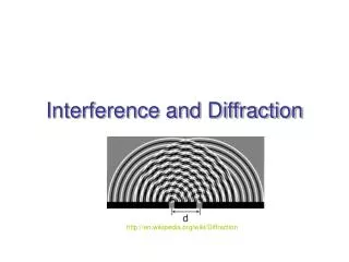
Learn about interference and diffraction, illustrated through superposition of waves. Explore constructive and destructive interference in the Young's double-slit experiment. Discover intensity distribution and path difference in wave interference.

E N D
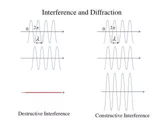
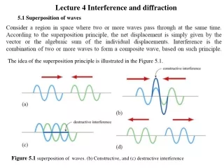
Lecture 4 Interference and diffraction 5.1 Superposition of waves The idea of the superposition principle is illustrated in the Figure 5.1. Figure 5.1 superposition of waves. (b) Constructive, and (c) destructive interference
(5.1) (5.2) The interference is constructive if the amplitude of is greater than the individual ones (Fig.5.1.b), and destructive if smaller (Fig.5.1.c.) (5.3) (5.4)
(5.5) (5.6) (5.7) (5.8)
The superposition of the wave is depicted in the figure below Figure 5.2 Superposition of two sinusoidal waves
5.2 Young double- slit experiment In 1801 Thomas Young carried out an experiment in which the wave nature of light was demonstrated. The schematic diagram of the double-slit experiment is shown in Figure 5.4 Figure 5.4 Young’s double-slit experiment
Figure 5.5 shows the ways in which the waves could combine to interfere constructively or destructively Figure 5.5 Constructive interference (a) at P, and (b) at P1. (c) destructive interference at P2 The geometry of the double-slit interference is shown in Figure 5.6 Figure 5.6 Double-slit experiment
Figure 5.6 Double-slit experiment (5.6) (5.9) (5.10)
Subtracting Eq. (5.9) from Eq.(5.10) yields (5.11) In the limit i.e, the distance to the screen is much greater than the distance between the slits, the sum of r1 and r2 may be approximated by and at difference becomes (5.12) Figure 5.7 Path difference between the two rays assuming
(5.13) (5.13) (5.14) (5.14) Figure 5.8
Figure 5.8 (5.15) (5.13) (5.14) (5.16) (5.17)
5.2 Intensity distribution Consider the double-slit experiment shown in Figure 5.9 Figure 5.9 Double-slit experiment (5.18) (5.19)
(5.20) (5.21) (5.22) (5.23)
(5.24) (5.25) (5.26) (5.27)
(5.28) (5.29) (5.30) (5.21) (5.31)
(5.13) (5.31)