Download

1 / 19
190 likes | 199 Views
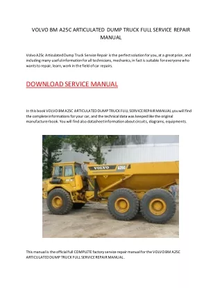
service repair manual

E N D
Service Manual Wartungshandbuch Manuel de maintenance WP2000S Series
TABLE OF CONTENT Printed in Germany
TABLE OF CONTENT Table of Content MA – SAFETY Safety Symbols used in the Manual ................................... M/P-MA-0000-001. General Maintenance and Repair Safety Notes................... M/P-MA-0000-001 - Maintenance and Repair ................................................. M/P-MA-0000-002 - Before Leaving the Truck................................................. M/P-MA-0000-002 - Before Carrying out Work on the Truck ............................ M/P-MA-0000-002 - Before Operating the Truck.............................................. M/P-MA-0000-002 Warnings and Labels on the Truck...................................... M/P-MA-0000-002 PAGE SER-NR. CUT REV. ITD – INTRODUCTION General ................................................................................. M/P-ITD-1720-501 - Operating instruction....................................................... M/P-ITD-1720-501 - Service training............................................................... M/P-ITD-1720-501 - Replacement parts orders............................................... M/P-ITD-1720-501 - Structure of the Manual .................................................. M/P-ITD-1720-501 - Page Numbers ................................................................ M/P-ITD-1720-502 Truck Data Numbering Sheet............................................... M/P-ITD-1720-504 PAGE SER-NR. CUT REV. M1 – LUBRICATION AND ADJUSTMENT Component Access .............................................................. M-1.0-1720-001 Jacking up the Truck............................................................ M-1.0-1720-001 Lifting by Crane.................................................................... M-1.0-1720-001 Lifting by Truck .................................................................... M-1.0-1720-002.......................................... Rev.1 09/00 Components ......................................................................... M-1.0-1720-003.......................................... Rev.1 09/00 Maintenance ......................................................................... M-1.1-1720-004 - Driver Participation ......................................................... M-1.1-1720-001 - Daily Maintenance Log.................................................... M-1.1-1720-001 - Recommended Lubricants and Oils ................................ M-1.1-1720-001 - Lubricants.................................................................. M-1.1-1720-001 - Cold Store Trucks ...................................................... M-1.1-1720-001 - Check and Maintenance Schedule.................................. M-1.2-1720-001 - Safety Reverse Switch - Functional Test......................... M-1.2-1720-003 ---------------------------------- Rev.1 09/00 - Grease items and grease intervals.................................. M-1.2-1720-010 ---------------------------------- Rev.1 09/00 Adjustment of castor- and drivewheel pressure................. M-1.5-1720-501 Torques................................................................................. M-1.9-0000-001 PAGE SER-NR. CUT REV. M2 – HYDRAULICS Hydraulic Symbols .............................................................. M-2.0-0000-001 Hydraulic System ................................................................. M-2.1-1720-001 - Removal ......................................................................... M-2.2-1720-001 - Hydraulikpump................................................................ M-2.3-1720-001 - Filter ............................................................................... M-2.3-1720-002 - Pressure Filter ........................................................... M-2.3-1720-002 - Suction and Return Filters ......................................... M-2.3-1720-002 - Oil Change................................................................. M-2.3-1720-002 - Commissioning .......................................................... M-2.3-1720-002 PAGE SER-NR. CUT REV. M3 – DRIVE UNIT Gear Unit............................................................................... M-3.1-1720-501 - Removal ......................................................................... M-3.1-1720-501 - Repair ............................................................................. M-3.1-1720-501 - Disassembly/Assembly ............................................. M-3.1-1720-503 - Installation ...................................................................... M-3.1-1720-505 PAGE SER-NR. CUT REV. Printed in Germany Rev.1 09/00 M-IDX-1720-501
TABLE OF CONTENT M4 – ELECTRICS Electrics - General................................................................ M-4.0-0000-001 - Wire Colour Codes .......................................................... M-4.0-0000-001 - Abbreviations.................................................................. M-4.0-0000-002 - Electrical Symbols.......................................................... M-4.0-0000-004 Electrical Components ........................................................ M-4.2-1720-500 - Transmitter (POT, FS, RS)............................................... M-4.2-1720-500 - Fast / Slow Travel Switch (HSS)...................................... M-4.2-1720-500 - Reverse Safety Switch (SAS)......................................... M-4.2-1720-500 - Brake Switch (BRS)........................................................ M-4.2-1720-500 - Override Switch (ORS).................................................... M-4.2-1720-503 - Lift / Lower Switch (RAS, LOS)....................................... M-4.2-1720-503 - Limit Switch (LMS) ......................................................... M-4.2-1720-503 - Horn Switch (HNS).......................................................... M-4.2-1720-503 - Key Switch (KYS) ........................................................... M-4.2-1720-503 - Emergency Disconnect................................................... M-4.2-1720-503 - Fuses (FU) ..................................................................... M-4.2-1720-503 - Temperature Switch (THS) (Freezer/Corrosion Truck only) M-4.2-1720-503 SEM 1 Traction Controller ................................................... M-4.3-1720-001 General ............................................................................. M-4.3-1720-001 - Precautionary Measures ............................................ M-4.3-1720-001 Operational Features......................................................... M-4.3-1720-001 - Speed Control............................................................ M-4.3-1720-001 - Reduced Speed Ranges ............................................ M-4.3-1720-001 - Downhill Speed Control .............................................. M-4.3-1720-001 - Regenerative Braking................................................. M-4.3-1720-001 - Anti-Roll-Down-Function............................................. M-4.3-1720-001 - Hourmeter.................................................................. M-4.3-1720-002 - Self Test .................................................................... M-4.3-1720-002 - Monitored Circuits...................................................... M-4.3-1720-002 Protective Devices............................................................ M-4.3-1720-003 - Polarity Protection ..................................................... M-4.3-1720-003 - Wiring Errors .............................................................. M-4.3-1720-003 - Temperature ............................................................... M-4.3-1720-003 - Start Sequence ......................................................... M-4.3-1720-003 - Protective Class ........................................................ M-4.3-1720-003 Maintenance ..................................................................... M-4.3-1720-003 Controller connections SEM-1........................................... M-4.3-1720-004 - Pin Layout SEM-1 ..................................................... M-4.3-1720-005 - Status-LED ................................................................ M-4.3-1720-006 Programmer ......................................................................... M-4.4-1720-001 General ............................................................................. M-4.4-1720-001 Operating Menu Controller SEM-1..................................... M-4.4-1720-002 - Operating Menu - Overview ....................................... M-4.4-1720-003 - Menu Functions ......................................................... M-4.4-1720-004 Settings and Alarms ......................................................... M-4.5-1720-001 - Menue PARAMETER CHANGE ................................. M-4.5-1720-001 - Menue TESTER......................................................... M-4.5-1720-004 - Menue ALARMS........................................................ M-4.5-1720-006 - Menue PROGRAM VACC .......................................... M-4.5-1720-008 - Menü CONFIG........................................................... M-4.5-1720-009 Traction Controller Safety Test ............................................ M-4.20-1720-001 Battery................................................................................... M-4.25-1720-001 Function............................................................................ M-4.25-1720-001 Reading the Electrolyte Level ........................................... M-4.25-1720-001 Replacing the Battery........................................................ M-4.25-1720-001 Removing the Battery ....................................................... M-4.25-1720-001 Charging the Battery ......................................................... M-4.25-1720-002 PAGE SER-NR. CUT REV. Printed in Germany M-IDX-1720-502
TABLE OF CONTENT Battery Discharge Indicator (BDI) ........................................ M-4.25-1720-002 - General........................................................................... M-4.25-1720-002 - Adjusting the Battery Discharge Indicator ....................... M-4.25-1720-002 Traction / Pump Motor Maintenance ................................... M-4.35-1720-001 - Access ........................................................................... M-4.35-1720-001 -Maintenance .................................................................... M-4.35-1720-001 M5 – BRAKE Brake..................................................................................... M-5.0-1720-501 - Function ......................................................................... M-5.0-1720-501 - Removal ......................................................................... M-5.0-1720-501 - Assembly ....................................................................... M-5.0-1720-502 - Air Gap Setting ............................................................... M-5.0-1720-502 - Brake Moment Setting .................................................... M-5.0-1720-503 - Testing the Brake ............................................................ M-5.0-1720-503 PAGE SER-NR. CUT REV. M6 – STEERING Multitask Handle - Springs for Return Function................ M-6.1-1720-501 - Adjustment ..................................................................... M-6.1-1720-501 - Removal ......................................................................... M-6.1-1720-501 - Assembly ....................................................................... M-6.1-1720-501 PAGE SER-NR. CUT REV. M7 – LIFTING MECHANISM Lift Linkage........................................................................... M-7.0-1720-501 - Fork Height Setting ......................................................... M-7.0-1720-002 PAGE SER-NR. CUT REV. M8 – CYLINDERS Lift Cylinders........................................................................ M-8.1-1720-501 - Operation ........................................................................ M-8.1-1720-501 - Removal ......................................................................... M-8.1-1720-501 - Inspection....................................................................... M-8.1-1720-503 - Replacing the Piston Seal............................................... M-8.1-1720-503 PAGE SER-NR. CUT REV. DIA – ELECTRICAL DIAGRAMS Standard Version.................................................................. M/P-DIA-1720-001 - Schematic Diagram ........................................................ M/P-DIA-1720-001 - Traction Controller ........................................................... M/P-DIA-1720-002 - Power Unit Circuit ........................................................... M/P-DIA-1720-004 - Control Handle Circuit ..................................................... M/P-DIA-1720-005 - Walkie- / Rider Circuit..................................................... M/P-DIA-1720-006 - Power Cables.................................................................. M/P-DIA-1720-007 - Main Harness ................................................................. M/P-DIA-1720-008 - Tiller Harness.................................................................. M/P-DIA-1720-009 Freezer- / Corrosion Trucks ................................................. M/P-DIA-1720-010 - Schematic Diagram ........................................................ M/P-DIA-1720-010 - Traction Controller ........................................................... M/P-DIA-1720-011 - Power Unit Circuit ........................................................... M/P-DIA-1720-013 - Control Handle Circuit ..................................................... M/P-DIA-1720-014 - Walkie- / Rider Circuit..................................................... M/P-DIA-1720-015 - Tiller Harness.................................................................. M/P-DIA-1720-016 PAGE SER-NR. CUT REV. HYD – HYDRAULIC SCHEMATIC Hydraulic Schematic ......................................................... M-HYD-1720-501 PAGE SER-NR. CUT REV. Printed in Germany M-IDX-1720-503
SAFETY Printed in Germany
SAFETY Safety Symbols used in the Manual General Maintenance and Repair Safety Notes To help guide you through the manual and to highlight particular danger areas, we have used graphic illustra- tions: DANGER Read the safety notices in the truck Mainte- nance and Operator's Manuals. DANGER Failure to do so could result in severe or fatal injuries to maintenance personnel and/or other persons. G This symbol indicates life-threatening risks Failure to comply with this notice may result in severe or fatal injuries to yourself or other people. G Motorised vehicles can be dangerous if maintenance and service are neglected. For this reason maintenance and inspections must be carried out at regular short intervals by trained personnel working to approved company guidelines. WARNING This symbol indicates the risk of serious injury and/or serious material damage. Maintenance and Repair Failure to comply with this notice may result in severe injuries to yourself or other people and/or serious material damage. G 1. Maintenance work must only be carried out in accordance with the test and maintenance pro- gram contained in the present Maintenance Manual and any applicable service notices. 2. Only qualified and authorised personnel may carry out work on the truck. CAUTION This symbol indicates the risk of minor injury and/or minor material damage. 3. Always keep fire extinguishers in good working condition. Do not approach fluid levels or leaks with a naked flame. Failure to comply with this notice may result in minor injuries to yourself or other people and/or minor material damage. G 4. To clean, use a non flammable, non combustible cleaning solution which is groundwater-neutral. Only carry out cleaning with an oil separator. Protect the electrical system from dampness. INFORMATION Contains additional information with supplementary notes and hints. 5. Keep the service area clean, dry and well-venti- lated. 6. Do not allow oil to penetrate the ground or enter the draining system. Used oil must be recycled. Oil filters and desiccants must be treated as special waste products. Relevant applicable regulations must be followed. OPTION These items relate to optional features not supplied with the standard version. OPTION Printed in Germany M/P-MA-0000-001
SAFETY Before Operating the Truck 7. Neutralise and thoroughly rinse any spilled battery fluid immediately. Check the safety devices. G 8. Keep the truck clean. This will facilitate the location of loose or faulty components. Get into the driver's seat. G 9. Make sure that capacity and data plates, warn- ings and labels are legible at all times. Check the operation of the lifting device, travel direction switch, speed control, steering, warning devices and brakes. G 10. Alterations or modifications by the owner or operator are not permitted without the express written authorisation from Crown. Warnings and Labels on the Truck During regular maintenance check that the warnings and labels on the truck are complete and legible. 11. Only use original Crown spare parts to ensure the reliability, safety and suitability of the Crown truck. Clean any illegible labels. G Before Leaving the Truck Replace any faulty or missing labels. G Stop the truck. G The order and meaning of the warnings and labels on the truck are described in section 10.9 of the parts manual. Lower the fork carriage fully. G Apply the parking brake. G Turn off the travel switch and remove the key. G Block all wheels when parking on an uneven surface. G Before Carrying out Work on the Truck Raise the truck to free the drive wheel. Press the emergency Stop button and disconnect the battery. G Prevent the truck from rolling away. G Before carrying out work on the hoist frame, the lift mast or on the fork carriage: Block these parts according to maintenance instructions in order to prevent them from dropping. G Only carry out operational testing when there is sufficient room to manoeuvre, to avoid the risk of injury to yourself and others. G Printed in Germany M/P-MA-0000-002
INTRODUCTION Printed in Germany
INTRODUCTION General series. Brochures can be obtained from your CROWN dealer or from the following address: The present manual is designed for Customer Service engineers who wish to familiarise themselves with the maintenance work required for the various truck components. CROWN Gabelstapler GmbH Kronstadter Str. 11 81677 Munich GERMANY Tel.: +49 (0)89 / 93 002 -0 Fax: +49 (0)89 / 93 002 -175 oder 133 It also contains troubleshooting sections which can be used to identify and remedy truck faults. INFORMATION This book is not an operating manual. It is designed solely for specialist personnel who have been trained and authorised to carry out the work described in the manual. Using the Manual The Maintenance Manual is written in three independent language blocks: English, German and French. This manual therefore contains fewer and less detailed warnings than the Operator's Manual, as the latter is aimed at persons who have very little or no prior experience at all. Each language block in turn is divided into chapters and sections. The table on the following page shows how the manual is structured. Operating Instructions This manual contains no operating instructions. An operating instructions manual is supplied with the vehicle. Additional copies can be ordered as required. S o i t c e n s n i a M e t n a n c e S o i t c e n D e s p i r c o i t n With the help of this manual you and your personnel will be able to ensure the long service life, operational safety and error free functioning of your CROWN vehicle. I D X e l b a T f o C e t n o t n M A y t e f a S Service Training T I D o r t n I d o i t c u n CROWN offers the appropriate vehicle related training for service personnel. Details on this training can be obtained from CROWN on request. M 1 L c i r b u o i t a n a n d u j d A t s m t n e M 2 H a r d y c i l u s Ordering Spare Parts The maintenance manual does not cover spare parts. These are listed in a separate manual. M 3 v i r D e t i n U M 4 e l E c i r t c l a Spare parts can be ordered by quoting: M 5 a r B k e The truck specification number G M 6 n i r e e t S g The truck model number G The truck serial number G M 7 M / t s a n i t f i L g M e c h s i n a m This information can be found on the truck's data plate. Only if this information is provided can the order be processed quickly, correctly and reliably. M 8 n i l y C r e d D I A e l E c i r t c l a a r g a i D m s Please refer to the Technical Specifications Sheet for the utilisable loads, technical data and dimensions for this H Y D H a r d y c i l u S c h e c i t a m A01M-gb Printed in Germany M-ITD-1720-501 1
INTRODUCTION Page Numbering in the Manual The page numbers are on the left and right-hand sides of the page footer. If a page has been modified since the last edition, a revision number will be found in the middle of the footer: 02 REV. 2/99 means the second amendment to this page in February 1999. The page numbers are not necessarily consecutive! The back page of the manual contains a print number in the following form: MS-WP2000S-GB-D-F 11/99 In this example, 11/99 is the edition date. A page beginning with M/P- is identical in both the maintenance and spare parts manuals: M/P-1.2-1720-001 M = Maintenance Manual P = Spare Parts Manual Chapter Page Number Section Truck Code e.g. 1.2 = Test and Maintenance Schedule (Pages which are identical for all trucks are given the code 0000 here) A page beginning with M- is only contained in the maintenance manual: M-1.2-1720-001 M = Maintenance Manual Chapter Page Number Section Truck Code e.g. 1.2 = Test and Maintenance Schedule (Pages which are identical for all trucks are given the code 0000 here) Printed in Germany M/P-ITD-1720-502 2
INTRODUCTION A page beginning with P- is only contained in the spare parts manual: P-1.0-1720-001 P = Spare Parts Manual Chapter Page Number Section e.g. 1.0 = Panels Truck Code (Pages which are identical for all trucks are given the code 0000 here) Printed in Germany M/P-ITD-1720-503 3
INTRODUCTION Model Number 2.0 WP 2030S – 3 – 2 – S Capacity Load Wheels 2.0 = 2000 kg S = Single T = Tandem Model Description F o r k L e n g t h WP = Electric Pedestrian Pallet Truck D a s h m m n i c h 1 3 6 2 9 9 5 Battery Box Size (l x w x h) 3 4 2 2030 = 360 Ah (288 x 624 x 627) 4 1 1 2 5 5 4 6 6 1 2 1 0 4 8 7 5 4 8 6 0 I02a-gb F o r k S p r e a d D a s h m m n i c h 1 1 8 2 5 2 0 2 0 3 5 4 0 2 2 4 6 7 0 2 7 I03a-gb Printed in Germany M/P-IT-1720-504 4
LUBRICATION AND ADJUSTMENT Printed in Germany
LUBRICATION AND ADJUSTMENT Component Access For regular maintenance purposes the drive unit, hy- draulic system, contactor panel etc. can be reached by removing the panel. The panel is fixed to the chassis by three screws, (Fig. 1515),located left , right and frontside. Remove the screws and lift the panel upward and then forward to remove it. Use the grip in the plastic-cover on top of the panel. Fastening screws Jacking up the Truck CAUTION Always support a raised truck with wooden blocks or other suitable equipment, thereby relieving the jack. The instruction "jack up the truck" always assumes that the raised truck will be lowered onto a secure surface. M1515 Lifting with a Crane Attach the straps to the hitch points as shown and ensure they cannot slide off. 1 Jacking Points 3 4 2 2000 WP 3 M1916 M1528 Printed in Germany Rev.1 09/00 M1.0-0000-0001 M-1.0-1720-001
LUBRICATION AND ADJUSTMENT Lifting by Truck DANGER Use a forklift with sufficient capacity and prevent the truck from sliding off the forks. Raise the forks to their maximum height. G Drive the forklift sideways underneath the truck (see diagram). G Place hard wooden blocks under the truck. G Secure the truck to prevent it from sliding off the forks. G Raise the truck. G 90 600 > 800 2000 WP Printed in Germany Rev.1 09/00 M1.0-0000-0002 M-1.0-1720-002
Thank you very much for your reading. Please Click Here. Then Get COMPLETE MANUAL. NO WAITING NOTE: If there is no response to click on the link above, please download the PDF document first and then click on it.
LUBRICATION AND ADJUSTMENT Components Control safety device Contactor panel Traction control sy- stem LH lift cylinder Horn Power safety device Pump motor Pressure Switch for load-sensitive speed reduction Lowering valve Hydraulic tank and in-built pump Magnetic brake Drive motor Drive wheel M1563 Printed in Germany Rev.1 09/00 M1.0-0000-0003 M-1.0-1720-003
LUBRICATION AND ADJUSTMENT Fast / Slow Travel Switch Lift / Lower Switch Horn button Travel Switch M1568 Safety Reverse Switch Battery Box Lock Model and Data Capacity Plate Emergency Dis- connect Hourmeter and Battery Discharge Display Key Switch M 1516 Printed in Germany Rev.1 09/00 M1.0-0000-0004 M-1.0-1720-004