Download
1 / 27
270 likes | 296 Views
service repair manual

E N D
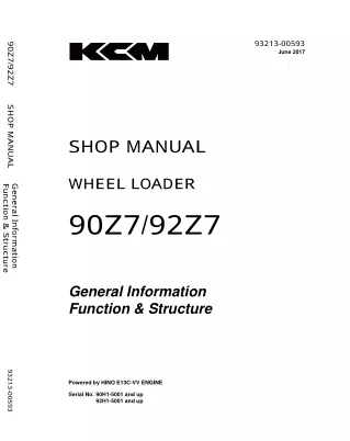
93213-00593 June 2017 90Z7/92Z7 S HOP MANUAL S HOP MANUAL WHEEL LOADER Func tion & S truc ture General Information 90Z7/92Z7 General Information Function & Structure 93213-00593 Powered by HINO E13C-VV ENGINE Serial No. 90H1-5001 and up 92H1-5001 and up ©2017 KCM Corporation. All rights reserved. Printed in Japan (K) (アメリカ用) (アメリカ用)
93213-00603 June 2017 90Z7/92Z7 S HOP MANUAL S HOP MANUAL WHEEL LOADER Troubleshooting Operational Performanc e Test 90Z7/92Z7 Operational Performance Test Troubleshooting 93213-00603 Powered by HINO E13C-VV ENGINE Serial No. 90H1-5001 and up Serial No. 92H1-5001 and up ©2017 KCM Corporation. All rights reserved. Printed in Japan (K) (アメリカ用) (アメリカ用)
93213-00593 SECTION 1 GENERAL Group 1 Specifications Group 2 Component Layout Group 3 Component Specifications SECTION AND GROUP CONTENTS SECTION 2 SYSTEM Group 1 Controller Group 2 Control System Group 3 ECM System Group 4 Hydraulic System Group 5 Electrical System SHOP MANUAL (Function & Structure) SECTION 3 COMPONENT OPERATION Group 1 Pump Device Group 2 Control Valve Group 3 Cooling Fan System Group 4 Steering Pilot Valve Group 5 Steering Valve Group 6 Pilot Valve Group 7 Charging Circuit Group 8 Drive Unit Group 9 Axle Group 10 Brake Valve Group 11 Others All information, illustrations and specifications in this manual are based on the latest product information available at the time of publication. The right is reserved to make changes at any time without notice. 90Z7/92Z7 F&S
93213-00603 SECTION 4 OPERATIONAL PERFORMANCE TEST Group 1 Introduction Group 2 Standard Group 3 Engine Test Group 4 Machine Performance Test Group 5 Component Test Group 6 Adjustment SECTION AND GROUP CONTENTS SHOP MANUAL (Troubleshooting) SECTION 5 TROUBLESHOOTING Group 1 Diagnosing Procedure Group 2 Monitor Group 3 e-Service Group 4 Component Layout Group 5 Troubleshooting A Group 6 Troubleshooting B Group 7 Air Conditioner All information, illustrations and specifications in this manual are based on the latest product information available at the time of publication. The right is reserved to make changes at any time without notice. 90Z7/92Z7(US)Trbl
93213-00652 September 2017 E13C-VV (90/92Z7) SHOP MANUAL Engine Diagnosis SHOP MANUAL HINO DIESEL ENGINE E13C-VV General Information General Information Engine Diagnosis 93213-00652 (For Kawasaki Wheel Loaders 90Z7 and 92Z7) ©2017 KCM Corporation. All rights reserved. Printed in Japan (K) (アメリカ用) (アメリカ用) Serial No. 90H1-5001 and up 92H1-5001 and up
1 GENERAL 2 STANDARD VALUE 3 PARTS TO BE PREPARED 4 ENGINE MOUNTING/DISMOUNTING 5 FUEL SYSTEM 6 EMISSION CONTROL 7 ELECTRICAL 8 INTAKE 9 ENGINE MECHANICAL 10 EXHAUST 11 COOLING 12 LUBRICATION 13 STARTING AND CHARGING 14 TURBOCHARGER 15 AIR COMPRESSOR 16 FAILURE DIAGNOSIS FOR EACH ENGINE STATUS 17 ENGINE DIAGNOSIS CODE For your information: This documentation does not contain any descriptions in regard to the hatched part "15. Air Compressor".
INTRODUCTION To The Reader This manual is written for trained and skilled technicians to provide technical information needed to maintain and repair this machine. Be sure to thoroughly read this manual for correct product information and service procedures. Additional References Please refer to the other materials (Operation and Maintenance Manual, parts catalog, engine technical material and Kawasaki Shop Manual, etc.) in addition to this manual. Manual Composition This manual consists the Technical Manual, the Workshop Manual and the Engine Manual. Information included in the Workshop Manual: Technical information needed for maintenance and repair of the machine, tools and devices needed for maintenance and repair, maintenance standards, and removal / installation and assembly / disassembly procedures. Information included in the Technical Manual: Technical information needed for machine pre-delivery and delivery, operation and activation of all devices and systems, operational performance tests, and troubleshooting procedures. Information included in the Engine Manual: Technical information needed for machine pre-delivery and delivery and maintenance and repair of the engine, operation and activation of all devices and systems, troubleshooting and assembly / disassembly procedures. Page Number Each page has a number, located on the center lower part of the page, and each number contains the following information: Example: Shop Manual: T 1-3-5 T Technical Manual 1 Section Number 3 Group Number 5 Consecutive Page Number for Each Group Workshop Manual: W 1-3-2-5 W Workshop Manual (disassembly and reassembly) 1 Section Number 3 Group Number 2 Sub Group Number 5 Consecutive Page Number for Each Group IN-01
INTRODUCTION Safety Alert Symbol and Headline Notations In this manual, the following safety alert symbol and signal words are used to alert the reader to the potential for personal injury or machine damage. d CAUTION: Indicated potentially hazardous situation which could, if not avoided, result in personal injury or death. d This is the safety alert symbol. When you see this symbol, be alert to the potential for personal injury. Never fail to follow the safety instructions prescribed along with the safety alert symbol. The safety alert symbol is also used to draw attention to component/part weights. To avoid injury and damage, be sure to use appropriate lifting techniques and equipment when lifting heavy parts. IMPORTANT: Indicates a situation which, if not conformed to the instructions, could result in damage to the machine. f NOTE: Indicates supplementary technical information. Units Used SI Units (International System of Units) are used in this manual. MKSA (Meter, Kilogram, Second, Ampere) system units and English units are also indicated in parentheses just behind SI units. Example: 24.5 MPa (250 kgf/cm2, 3560 psi) A table for conversion from SI units to other system units is shown below for reference purposes. Quantity Length To Convert From mm mm L L m3 kg N N N·m MPa MPa kW kW °C km/h min-1 L/min mL/rev Into in ft US gal US qt yd3 lb kgf lbf kgf·m kgf/cm2 psi PS HP °F mph rpm US gpm cc/rev Multiply By 0.03937 0.003281 0.2642 1.057 1.308 2.205 0.10197 0.2248 0.10197 10.197 145.0 1.360 1.341 °C×1.8+32 0.6214 1.0 0.2642 1.0 Volume Weight Force Torque Pressure Power Temperature Velocity Flow rate fNOTE: The numerical value in this manual might be different from the above-mentioned table. IN-02
Symbol and Abbreviation Symbol and Abbreviation Symbol / Abbreviation S/M T/C T/M MC Name Explanation Shop Manual Torque Converter Transmission Main Controller Shop Manual Torque Converter Transmission Main controller. MC controls the engine, pump, and valve according to the machine operating condition. Engine controller. ECM controls fuel injection amount according to the machine operating condition. Variable turbo controller. VGS is an exhaust turbo charged system to supercharge the exhaust energy while running the engine at slow idle speed. VGS optimizes the turbine rotation, improves the performance at slow-speed torque and the acceleration, reduces fuel consumption, and reduces particulate matter (PM) by adjusting the nozzle opening of turbine housing. CAN communication. CAN is a serial communications protocol internationally-standardized by ISO (International Organization for Standardization). Air conditioner. ECM Engine Control Module VGS VGT Variable Geometry System controller Variable Geometry Turbo CAN Controller Area Network A/C HVAC OP, OPT MPDr. Air Conditioner Heating, Ventilation, and Air Conditioning Option Maintenance Pro Dr. Optional component. MPDr. is software that troubleshooting, monitoring, and adjustment. Auto idling-stop function Warm up after starting the engine Slow idle engine speed. Front attachment, such as bucket A/I, A/S WU Li ATT Auto Idling-Stop Warming-Up Low (Slow) Idle Attachment SY-1
Symbol and Abbreviation Symbol / Abbreviation DPF Name Explanation Diesel Particulate Filter (Filtration) DPF is a filter which removes particulate matter (PM) including the toxic substance of exhaust gas of the diesel engine. Exhaust particulate removal equipment. DPR Diesel Particulate Active Reduction System DPR moves exhaust gases through a catalyst that oxidizes hydrocarbons to form carbon dioxide, water and a change in temperature. DPR captures PM (soot) and burns down with a controlled temperature and regenerates the filter. Diesel Oxidation Catalyst Oxidation catalyst for the diesel engine. Diesel oxidation catalyst oxidizes unburned fuel and raises exhaust temperature. Catalyzed Soot Filter Filter. The filter traps, burns, and remove particulate matter (PM) by using high-temperature-exhaust gas with diesel oxidation catalyst. Catalyst is applied onto the filter. This advances PM burning. Particulate Matter Particulate matter. Exhaust Gas Recirculation The EGR control re-circulates a part of exhaust gas in the intake manifold and combines it with intake-air. Therefore, combustion temperature is lowered and generation of oxide of nitrogen (NOx) is controlled. DOC CSF PM EGR SY-2
SECTION 1 GENERAL CONTENTS Group 1 Specifications 90Z7 Specifications ............................................................T1-1-1 92Z7 Specifications ............................................................T1-1-2 Weight of Main Components .........................................T1-1-3 Group 2 Component Layout Main Component (90Z7) (Overview) ...........................T1-2-1 Main Component (90Z7) ..................................................T1-2-2 Main Component (92Z7) (Overview) ...........................T1-2-4 Main Component (92Z7) ..................................................T1-2-5 Electric Component Layout (Overview)......................T1-2-7 Electrical System (Cab) ......................................................T1-2-8 Controller and Relays ...................................................T1-2-9 Right Console ................................................................T1-2-10 Monitor and Switches ................................................T1-2-11 Monitor Panel ...............................................................T1-2-12 Electrical System (Relays) ...............................................T1-2-13 Electrical System (Around Hydraulic Oil Tank)........T1-2-14 Electrical System (Around Fuel Tank) .........................T1-2-15 Engine ...................................................................................T1-2-16 Exhaust Filter/Air Cleaner ..............................................T1-2-17 Hydraulic Pump .................................................................T1-2-18 Main Pump .....................................................................T1-2-18 Accessory Pump ...........................................................T1-2-18 Transmission and Torque Converter Assembly ......T1-2-19 Multiple Control Valve .....................................................T1-2-20 Unloader Valve (Brake Charge Valve) .........................T1-2-21 Flow Regulator Valve .......................................................T1-2-21 Combination Valve ...........................................................T1-2-21 Ride Control Valve (Option) ...........................................T1-2-21 Steering Valve .....................................................................T1-2-22 Secondary Steering Pump (Option) ...........................T1-2-22 Front Axle .............................................................................T1-2-23 Group 3 Component Specifications Engine .....................................................................................T1-3-1 Engine Accessories .............................................................T1-3-4 Hydraulic Component .......................................................T1-3-6 Electrical Component ......................................................T1-3-11 90Z7/92Z7 F&S
SECTION 1 GENERAL Group 1 Specifications 90Z7 Specifications 90Z7-FK-GSC Bucket type Bucket Capacity: heaped Operating Weight Tipping Load (Full Turn) Engine A: Overall Length B: Overall Width (Bucket) C: Overall Height D: Wheel Base E: Tread F: Ground Clearance G: Bucket Hinge Height H: Dumping Clearance (45 °) I: Dumping Reach (45 °) R1: Minimum Rotation Radius R2: Bucket Carry Position Travel Speed Forward/Reverse Transmission Speeds (F/R) Articulation Angle (Left/Right) deg Tire Size Unit m3 (Y3) kg (lb) kg (lb) GSC 4.2 (5.5) 24550 (54125) 16270 (35870) HINO E13C-V V Diesel 9055 (356) 3100 (122) 3530 (139) 3450 (136) 2230 (88) 505 (20) 4425 (174) 3075 (121) 1340 (53) 6270 (247) 7340 (289) 37.0/37.0 (23.0/23.0) 4/4 37 26.5-25-20PR (Bias) LSC 4.7 (6.1) 24870 (54830) 15870 (34990) HINO E13C-V V Diesel 9140 (360) 3100 (122) 3530 (139) 3450 (136) 2230 (88) 505 (20) 4425 (174) 3010 (119) 1400 (55) 6270 (247) 7365 (290) 37.0/37.0 (23.0/23.0) 4/4 37 26.5-25-20PR (Bias) mm (in) mm (in) mm (in) mm (in) mm (in) mm (in) mm (in) mm (in) mm (in) mm (in) mm (in) km/h (mph) - ( ° ) - fNOTE: BOC (Bolt-On Cutting Edge) ? These specifications are subject to change without notice. T1-1-1
SECTION 1 GENERAL Group 1 Specifications 92Z7 Specifications 90Z7-FK-GSC Bucket type Bucket Capacity: heaped Operating Weight Tipping Load (Full Turn) Engine A: Overall Length B: Overall Width (Bucket) C: Overall Height D: Wheel Base E: Tread F: Ground Clearance G: Bucket Hinge Height H: Dumping Clearance (45 °) I: Dumping Reach (45 °) R1: Minimum Rotation Radius R2: Minimum Rotation Radius Travel Speed Forward/Reverse Transmission Speeds (F/R) Articulation Angle (Left/Right) deg Tire Size Unit m3 (Y3) kg (lbs) kg (lbs) GSC 4.8 (6.3) 26840 (59170) 17950 (39570) HINO E13C-V V Diesel 9275 (365) 3170 (125) 3530 (139) 3550 (140) 2230 (88) 505 (20) 4525 (178) 3165 (125) 1445 (57) 6420 (253) 7565 (298) 36.4/36.4 (22.6/22.6) 4/4 37 26.5-25-20PR (Bias) LSC 5.2 (6.8) 27090 (59725) 17070 (37635) HINO E13C-V V Diesel 9365 (369) 3170 (125) 3530 (139) 3550 (140) 2230 (88) 505 (20) 4525 (178) 3100 (122) 1510 (59) 6420 (253) 7590 (299) 36.4/36.4 (22.6/22.6) 4/4 37 26.5-25-20PR (Bias) mm (in) mm (in) mm (in) mm (in) mm (in) mm (in) mm (in) mm (in) mm (in) mm (in) mm (in) km/h (mph) - ( ° ) - fNOTE: BOC (Bolt-On Cutting Edge) ? These specifications are subject to change without notice. T1-1-2
SECTION 1 GENERAL Group 1 Specifications Weight of Main Components Item Approx. Weight (kg) 1940 (90Z7) 2055 (92Z7) 1890 (90Z7) 1970 (92Z7) 290 (90Z7) 310 (92Z7) 310 80 40 x 2 (RH, LH) 40 40 (RH), 35 (LH) 20 x 2 120 (Front) 30 (Middle) 90 (Rear) 165 325 1510 (90Z7) 1610 (92Z7) 1740 (90Z7) 1900 (92Z7) 425 (90Z7) 490 (92Z7) 96 (90Z7) 102 (92Z7) 720 x 2 (90Z7) 1475 x 2 (92Z7) 570 (90Z7) 675 (92Z7) 95 45 x 2 670 x 4 Approx. Weight (lb) 4280 (90Z7) 4530 (92Z7) 4170 (90Z7) 4345 (92Z7) 640 (90Z7) 685 (92Z7) 685 180 90 x 2 (RH, LH) 90 90 (RH), 80 (LH) 45 x 2 260 (Front) 60 (Middle) 200 (Rear) 365 720 3335 (90Z7) 3545 (92Z7) 3840 (90Z7) 4190 (92Z7) 940 (90Z7) 1080 (92Z7) 210 (90Z7) 225 (92Z7) 1585 x 2 (90Z7) 3250 x 2 (92Z7) 1260 (90Z7) 1490 (92Z7) 210 100 x 2 1480 x 4 Remarks Unit Name Part Name Front chassis Rear chassis Floor board Engine room assy Rear grill assy Side cover (main) Roof Deck Fender Radiator guard + wind shield With handrails. (See D&R S/M W3-4-2-9.) Belly guard Option Hydraulic tank Fuel tank Chassis The weight differs depending on the bucket type. Bucket (GSC) Lift Arm (Boom) Z-Lever (Bell Crank) Bucket Link Counter weight ROPS Cab mount Battery box Battery Tire 26.5-25-20PR (L3) with wheel rim T1-1-3
SECTION 1 GENERAL Group 1 Specifications Item Approx. Weight (kg) 1260 1035 185 50 70 23 1320 (90Z7) 1580 (92Z7) 1510 (90Z7) 1780 (92Z7) 110 (TPD assy) 112 (LSD assy) 65 15 70 85 10 22 5.5 90 7.5 10 11 13 12.5 12 18 x 2 185 x 2 270 40 x 2 13 Approx. Weight (lb) 2780 2285 410 110 155 50 2910 (90Z7) 3485 (92Z7) 3330 (90Z7) 3925 (92Z7) 80 (TPD assy) 83 (LSD assy) 145 35 155 190 20 50 12 195 16.5 20 25 30 27.5 26.5 40 x 2 410 x 2 595 90 x 2 30 100 125 Remarks Unit Name Part Name Engine Transmission assy Radiator mount Cooling unit mount Second propeller shaft Third propeller shaft Drive unit (See D&R S/M W4-2.) Radiator + Torque converter oil cooler Hydraulic oil cooler + Air cooler Excluding tires and oil (See D&R S/M W4-3.) Excluding tires and oil, Including axle supports (See D&R S/M W4-3.) Front axle assy Power line Rear axle assy Differential assy See D&R S/M W4-3. Fan assy Air cleaner Exhaust filter assy Multiple control valve Loading Pilot valve Steering valve Steering pilot valve Main Pump Accessory Pump Fan motor Fan control valve Unloader valve Combination valve assy Brake valve assy Brake accumulator Lift arm cylinder Bucket cylinder Steering cylinder Ride control valve Ride control accumulator 45 Accumulator bracket Excluding fan motor Engine accessory, DPF (50 kg, 110 lb) OrbitrolTM Brake charge valve Hydraulic system Excluding oil Excluding oil Excluding oil Option Option Option 55 fNOTE: The weights are for reference and not the exact values. IMPORTANT: When handling each component, be careful and prepare tools of enough capacity considering additional weight. T1-1-4
SECTION 1 GENERAL Group 2 Component Layout Main Component (90Z7) [ Overview ] 90TNED-01-02-16 90TNED-01-02-17 1- 2- 3- Bucket Bell Crank (Lever) Bucket Cylinder 4- Front Combination Light (Headlight, Turn Signal Light, Clearance Light, Hazard Light) Front Work Light Rear Work Light 7- Rear Combination Light (Turn Signal Light, Hazard Light, Tail Light, Brake Light, Backup Light) Lift Arm (Boom) 9- 10- Bucket Link Lift Arm (Boom) Cylinder 5- 6- 8- T1-2-1
SECTION 1 GENERAL Group 2 Component Layout Main Component (90Z7) 90TNED-01-02-32 1- 2- 3- 4- 5- 6- 7- 8- Fan Motor Radiator Inter Charge Air Cooler Coolant Level and Surge Tank Exhaust Filter/Muffler Air Cleaner Service Brake Accumulator Brake Charge (Unloader) Valve 9- 10- Brake Valve 11- Steering Pilot Valve (Orbitrol) 12- Pilot Valve 13- Steering Valve 14- Loading Control Valve 15- Stop Valve 16- Flow Regulator Valve Manifold Valve 17- Engine Oil Filter 18- T/M Oil Filter 19- Hydraulic Tank 20- Engine 21- Fuel Filter 22- Torque Converter Cooler 23- Hydraulic Oil Cooler 24- Steering Accumulator 25- Reducing Valve 26- Solenoid Valve (for DPF Regeneration) 27- Fan Control Valve 28- Ride Control Accumulator (Option) 29- Ride Control Valve (Option) 30- Parking Brake Accumulator T1-2-2
SECTION 1 GENERAL Group 2 Component Layout Main Component (90Z7) 90TNED-01-02-27 1- 2- 3- 4- Front Axle Second (Front) Propeller Shaft Steering Cylinder Hydraulic Pump 5- 6- 7- Transmission Rear Axle Third (Rear) Propeller Shaft 8- Pressure Sensor (Brake Secondary Pressure) (for declutch) Fuel Tank 10- Fuel Pre-Filter 9- T1-2-3
SECTION 1 GENERAL Group 2 Component Layout Main Component (Overview) [ 92Z7 ] 92Z7-01-02-01 92Z7-01-02-02 1- 2- 3- Bucket Bell Crank (Lever) Bucket Cylinder 4- Front Combination Light (Headlight, Turn Signal Light, Clearance Light, Hazard Light) Front Work Light Rear Work Light 7- Rear Combination Light (Turn Signal Light, Hazard Light, Tail Light, Brake Light, Backup Light) Lift Arm (Boom) 9- 10- Bucket Link Lift Arm (Boom) Cylinder 5- 6- 8- T1-2-4
SECTION 1 GENERAL Group 2 Component Layout Main Component (92Z7) 92Z7-01-02-06 1- 2- 3- 4- 5- 6- 7- 8- Fan Motor Radiator Inter Charge Air Cooler Coolant Level and Surge Tank Exhaust Filter/Muffler Air Cleaner Service Brake Accumulator Brake Charge (Unloader) Valve 9- 10- Brake Valve 11- Steering Pilot Valve (Orbitrol) 12- Pilot Valve 13- Steering Valve 14- Loading Control Valve 15- Stop Valve 16- Flow Regulator Valve Manifold Valve 17- Engine Oil Filter 18- T/M Oil Filter 19- Hydraulic Tank 20- Engine 21- Fuel Filter 22- Torque Converter Cooler 23- Hydraulic Oil Cooler 24- Steering Accumulator 25- Reducing Valve 26- Solenoid Valve (for DPF Regeneration) 27- Fan Control Valve 28- Ride Control Accumulator (Option) 29- Ride Control Valve (Option) 30- Parking Brake Accumulator T1-2-5
SECTION 1 GENERAL Group 2 Component Layout Main Component (92Z7) 92Z7-01-02-04 1- 2- 3- 4- Front Axle Second (Front) Propeller Shaft Steering Cylinder Hydraulic Pump 5- 6- 7- Transmission Rear Axle Third (Rear) Propeller Shaft 8- Pressure Sensor (Brake Secondary Pressure) (for declutch) Fuel Tank 10- Fuel Pre-Filter 9- T1-2-6
SECTION 1 GENERAL Group 2 Component Layout Electric Component Layout (Overview) [ 90Z7 ] 90TNED-01-02-28 [ 92Z7 ] 92Z7-01-02-05 1- 2- 3- 4- Bucket Proximity Switch Lift Arm Angle Sensor ECM (Engine Control Module) Components Related with Cab (Refer to T1-2-8) 5- Components Related with Hydraulic Tank (Refer to T1- 2-14) Components Related with Engine (Refer to T1-2-16) 7- 8- 9- Backup Alarm Battery Components Related with Fuel Tank (Refer to T1-2-15) 10- Components Related with Hydraulic Pump (Refer to T1-2-18) 11- Secondary Steering Pump (Option) 6- T1-2-7
SECTION 1 GENERAL Group 2 Component Layout Electrical System (Cab) 7 90Z7-01-02-01 90TNED-01-02-29 1- 2- 3- 4- Radio Upper Switch Panel (Option) Speaker Rear Wiper Motor 5- Components in Right Console (Refer to T1-2-10) Components Related with Controllers and Relays (Refer to T1-2-9) 7- 8- 9- Outside Temperature Sensor Brake Lamp Switch Front Wiper Motor 10- Components Related with Monitor and Switches (Refer to T1-2-11) 6- T1-2-8
Thank you very much for your reading. Please Click Here. Then Get COMPLETE MANUAL. NO WAITING NOTE: If there is no response to click on the link above, please download the PDF document first and then click on it.
SECTION 1 GENERAL Group 2 Component Layout Controller and Relays 92TNED-01-02-30 1- 2- 3- 4- 5- 6- 7- 8- 9- 10- Bucket Leveler Relay Monitor Controller Flasher Relay Air Conditioner Controller MC (Main Controller) Main Relay 1 Main Relay 2 Head Light Relay (Left) Head Light Relay (Right) High-Beam Relay 11- Back Lamp and Alarm Relay 12- Work Light Relay (Front) 13- Work Light Relay (Rear) 14- Right Turn Signal Light Relay 15- Horn Relay 16- Starter Cut Relay 17- Parking Brake Relay 1 18- Parking Brake Relay 2 19- Pilot Shut-Off Relay 20- Brake Light Relay 21- Load Dump Relay 22- Neutral Relay 23- Left Turn Signal Light Relay 24- Front Washer Relay 25- Rear Wiper Relay 26- Rear Washer Relay 27- Engine Actuator Relay 28- Engine ECM Main Relay 29- Exhaust Filter Relay 1 30- Exhaust Filter Relay 2 31- Work Light Relay (Front) (Option) 32- Work Light Relay (Rear) (Option) 33- Fuse Box 34- MPDr. Connector 35- Secondary Steering Relay (Option) T1-2-9
SECTION 1 GENERAL Group 2 Component Layout Right Console 20 Fingertip Control Type 4 5 6 7 8 9 3 10 21 11 12 2 1 22 19 18 13 14 15 1716 MNEC-01-042 MNEC-01-041 Multi-Function Joystick Type (Option) 22 20 1 5 6 7 8 23 10 11 12 25 24 26 27 19 13 14 15 1716 MNEC-01-044 MNEC-01-043 1- Auxiliary Control Lever (Option) Bucket Control Lever Lift Arm Control Lever Forward/Reverse Switch Control Lever Lock Switch Declutch Position Switch Travel Mode Selector Switch Power Mode Switch Forward/Reverse Selector Switch 10- Fan Reverse Rotation Switch 11- Hydraulic Coupler Switch (Option) 12- Auxiliary 13- Secondary Steering Operation Check Switch (Option) 14- Exhaust Filter Switch 9- 15- Auxiliary 16- Auxiliary 17- Ride Control Switch (Option) 18- Hold Switch 19- Right Console Slide Lever 20- DSS (Down Shift Switch) 21- Horn Switch 22- Quick Power Switch 23- Forward/Reverse Selector Switch 24- Forward/Reverse Switch 25- Multi-Function Joystick Lever 26- Hold Switch (Under the Lever) 27- Horn Switch (Under the Lever) 2- 3- 4- 5- 6- 7- 8- T1-2-10
SECTION 1 GENERAL Group 2 Component Layout Monitor and Switches 90TNED-01-02-29a 6 7 8 9 2 3 4 5 1 MNEC-01-037 MNEC-01-038 1- 2- 3- 4- Front/Rear Wiper Switch Hazard Switch Work Light Switch Parking Brake Switch 5- Forward/Reverse Lever/Shift Switch Monitor Panel (Refer to T1- 2-12) 7- Turn Signal Lever/Light Switch/High-Low Beam Switch Multi-Function Monitor/Air Conditioner Switch Panel 9- Key Switch 6- 8- T1-2-11