Download
1 / 22
220 likes | 232 Views
service repair manual

E N D
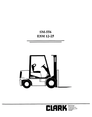
SM-556 ESM 12-25 Copyrighted Material Intended for CLARK dealers only Do not sell or distribute
SERVICE MANUAL SM556 CONTENTS PAGE GROUP ii . . . III iv iv Foreword How to Use this Manual Pictorial Index Safety and Operational Checks Recommended Planned Maintenance and Lubricatiin Schedule Safety Signs and Messages User Safe Maintenance Practices V vi vi PAGE GROUP PM-1 12-01-l 13-01-f 13-02-l 14-01-l 16-01-l 16-02-l 16-03-l 16-04-l 16-23-l 17-01-l 19-01-l 19-02-l 20-01-l 22-01-l 22-02-l 23-01-l 23-02-l 23-03-l 23-04-l 25-01-l 26-01-l 26-02-l 26-03-l 29-01-l 30-01-l 31-01-l 32-01-l 33-01-l 34-01-l 34-9R-1 38-01-l 38-02-l 39-01-l 39-02-l 40-01-l 40-02-l 40-03-l Planned Maintenance Program Battery Removal & Maintenance Accetkator and Directional Control System Main Pump Motor Switch Check and Adjustment Electrical System and Components Electric Motor General Maintenance Drive Motor Main Pump Motor Steer Pump Motor Drive Motor Overhaul Drive Motor Cut-Cut Switch Check and Adjust Control Panel Control Panel Operation and Troubleshooting Drive Axle Cushion Wheels and Tires Pneumatic Drive Tire and Wheel Maintenance Hydraulic Brake System Brake Master Cyiinder Brake Slave Cylinder Service Brake Steering Gear Steering Axle Power Steering Pump Steer Torque Generator Main Hydraulic Pump Main Hydraulic Valve Hydraulic System Tilt Cylinder Selector Solenoid Valve Upright UprigM Removal Counterweight Machine Jacking & Blocking Overhead Guard Sheet Metal and Trim Truck Data Plate and Decals Truck Data and Specifications Hydraulic and Electric Diagrams PM 12. . 13 13 14 16 16 16 16 16 17 19 19 20 22 22 23 23 23 23 25 26 26 26 29 30 31 32 33 34 34 36 38 39 39 40 40 40 ’ Rev Jan 90 SM556 i Copyrighted Material Intended for CLARK dealers only Do not sell or distribute
FOREWORD Clark Equipment Company welcomes you to the growing group of professional people who own, operate and maintain Clark lift trucks. This manual wiil familiarize you with service maintenance and overhaul information about your new truck. It has been especially prepared to help you maintain your Clark lift truck in an efficient and safe operating condition. Regular, correct maintenance and care of your lift truck is not only important for full and efficient truck life, it is essential for your safety. A faulty Iii truck is a potential source of danger to the operator, and to other personnel working near it. The importance of maintaining your Iii truck in a safe operating condii servicing it regularly and, when necessary, repairing it promptly cannot be emphasized too strongly. by To assist you in keeping your fii truck in good operating condition, this manual includes an outline of planned maintenance (PM) procedures that are considered essential to the life and safe performance of your truck. Brief procedures for inspections, operational checks, deaning, tubncatiin, and adjustments are included for your reference. . ,. Clark recommends that a planned maintenance and safety inspection program (PM) be performed by a trained and authorized mechanic on a regular basis. The PM program provides the opportunity to make thorough inspections and checks on the safe condition of your truck. Necessary adjustments and repairs can be done during the PM, which will increase the life of components and reduce unscheduled downtime. The need for major adjustments, repairs, or replacements is found and corrections made as required, not after failure has occurred. SM556 ii Copyrighted Material Intended for CLARK dealers only Do not sell or distribute
HOW TO USE THIS MANUAL This manual is intended to be used by persons who are trained and authorized to do lift truck maintenance. The recommended procedures for routine servicing and adjustments as well as for removal and overhaul of major components of the truck are outlined. It is written to show and describe the adjustment, removal, disassembly, inspection, repair, and assembly steps that are normally required to service these compo- nents. The detailed procedures are arranged in sequence by numbered GROUP and Section. The GROUP numbers are the same as the component group in the Master Parts Book. Each GROUP has its own Table of Contents, so that you can find the various topics within more easily. If you cannot find a topic in the Table of Contents, check the Index at the back of the manual. Component specifications, information notes and safety messages are included at the proper step of each procedure. To be better prepared to do the necessary service work, please take time to read the entire procedure, including any speciaf instructions; before doing anywork. Speciffcations of selected truck components are included at the back of the manual for easy reference. Also refer to the Operator’s Manual, located on the truck, for additional information and instructions on the operation and maintenance of your truck. If you have need for more information on the care and repair of your truck, please contact your authorized Clark dealer. . ,_ . NOTICE - The descriptions and specifications included in this manual were in effect at the time ofprinting. Clark Equipment Company reserves the right to make improvements and changes in specifications or design, with- out notice and without incurring obligation. Please check w2h your authorized CLARK dealer for information on possible updates or revisions. 0 Clark Equipment Company 1989 SM556 iii Copyrighted Material Intended for CLARK dealers only Do not sell or distribute
PICTORIAL INDEX 1. Control Handle 2. Traction Control Panel 3. Lift Pump & Motor 4. Steer Pump & Motor 5. Service Brake 6. Drive Motors (2) 7. SumpTank 8. Battery 9. Steer Axle & Housing 1 O.Steer Torque Generator 11. Brake Reservoir 12. Steer Control and Valve 5 6 SAFETY AND OPERATIONAL CHECKS Daily Inspection - CMWV Checktruckforobvic__ Check / clean battery terminals Check electrolyte level Check capacity, wamina plates. decal Check condition of ti, res and wheels and remove embedded objects Check wheel lug nuts _-_. J S-10 hours ABCDE 0 Q . XIS damage and leaks __...__ I II I I 0 I I I bn and bolts tration and other warning V devices Check steering operation Check brake operation Check directional and speed control operation Check lift, tilt, ai nd aux. operation Check upright, lift ch( ains and fasteners Check load backrest extension and forks 0 0 . _._ SM556 iv Copyrighted Material Intended for CLARK dealers only Do not sell or distribute
RECOMMENDED PLANNED MAINTENANCE and LUBRICATION SCHEDULE Recommended Planned Maintenance Interval A = 8-l 0 hours daily B = 50-250 hours or every month c= 450-500 hours or every 3 months D = 900-l 000 hours or every 6 months E = 2000 hours or every year Copyrighted Material Intended for CLARK dealers only Do not sell or distribute Rev Jan ‘96 SM556 v
User Safe Inspection Practices Safety Signs and Safety Messages The following instructions have been prepared from current industry and government safety standards applicable to industrial maintenance. They are listed hereforthe reference and safety of all workers during inspection / maintenance operations. When in doubt of any inspection maintenance procedures, please contact your local CLARK dealer. lmproperorcareless techniques cause accidents. Don’t take chances with incorrect or damaged equipment. READ and UNDERSTAND the procedures for safe driving and maintenance outlined in this manual. truck operations and / STAY ALERT! Follow safety rules, regulations and procedures. Accidents can be avoided by recognizing dangerous procedures or situations before they occur. 1 .Powered industrial trucks can become hazardous if maintenance is neglected. maintenance facilities, trained personnel and procedures shall be provided. DRIVE AND WORK SAFELY and follow the safety signs and their messages displayed on the truck and in this manual. Therefore, suitable SAFETY SIGNS and MESSAGES are placed in this manual and also on the lift truck to provide instructions and to identify specific areas where potential hazards exist and special precautions should be taken. Be sure you know and understand the meaning of these instruc- tions, signs and messages. Damage to the truck or death or serious injury to you or other persons may result if these messages are not followed. 2. Maintenance and inspection of all powered industrial trucks shall be done in conformance manufacturers recommendations. with the 3. A scheduled planned maintenance, lubrication and inspection system shall be followed. 4. Only trained and authorized personnel shall be permitted to maintain, repair, adjust and inspect industrial trucks and in accordance with the manufacturer’s specifications. NOTICE This message is used when special informa- tion is required to clarify procedures or identify components pertaining to the truck. 5. Properly ventilate work area, vent exhaust fumes, keep shop clean and floor dry. IMPORTANT This message is used when additional atten- tion is required for proper operation or mainte- nance of the truck. A This message is used as a reminder of safety practices which can result in personal injury if proper precautions are not taken. A WARNING This message is used when a hazard exists which can result in injury or death, if proper precautions are not taken. A DANGER This message is used when an extreme hazard exists which will result in death or serious injury if proper precautions are not taken. 6. Avoid fire hazards and have fire protection equipment present in the work area. Do not use an open flame to check electrolyte level. Do not use open pans of fuel or flammable cleaning fluids for cleaning parts. ! CAUTION 7.Before Starting To Work On Truck: a) Raise drive wheel free of floor or disconnect power source and use blocksorother positive truck positioning devices. b) Put blocks under the load-engaging innermast( or chassis before working on them. c) Disconnect battery before working on the electrical system. means, 8. Operation of the truck to check performance must be conducted in an authorized, safe, clear area. Copyrighted Material Intended for CLARK dealers only Do not sell or distribute SM556 vi Rev Jan ‘96
connections must be inspected and maintained in conformance with good practices. Special attention must be paid to the condition of electrical insulation. 9. Before Starting to Drive the Truck: a) Be in operating position. b) Turn on power. c) Check functioning of lift and tilt systems. d) Check directional and speed controls. e) Check steering. 9 Check brakes. g) Check warning devices. h) Check any load handling attachments. 17. To avoid injury to personnel or damage to the equipment, consult the manufacturers procedures in replacing contacts on any battery. 18. Industrial trucks must be kept in a clean condition to minimize fire hazards and help in the detection of loose or defective parts. 10. Before Leaving the Truck: a) Stop truck. b) Fully lower forks or attachment device. c) Allow directional control to return to neutral. d) Turn off the control / ignition switch. e) Chock wheels if truck must be left on an incline. 19. Modiiiations and safe truck operation must not be done without the manufacturer’s prior written approval. Capacity, operation and maintenance instruction plates, tags or decals must be changed accordingly. and additions that affect capacity 11. Brakes, steering mechanisms, control mechanisms, warning devices, lights, lift overload devices, guards and safety devices, lift, reach and rotation mechanisms, and frame members must be carefully and regularly inspected and maintained in a safe operating condition. 20. Care must be taken to assure that all replacement parts, including tires, are interchangeable with the original parts and of a quality at least equal to that provided in the original equipment. Parts, including tires, are to be installed per the manufacturers procedures. Always use genuine CLARK or CLARK - approved parts. ‘12. Special trucks or devices designed and approved for hazardous area operation must receive special attention to ensure that maintenance preserves the original, approved safe operating features. ; 21. When removing tires, follow industry safety practiced. Most important, deflate pneumatic tires completely prior to removal. Following assembly of tires on multi-piece rims, use a safety cage or restraining device while inflating. 13. All hydraulic systems must be regularly inspected and maintained in conformance with good practices. Tilt and lift cylinders, valves and other similar parts must be checked to assure that “drift” or leakage has not developed to the extent that it would create a hazard. 22. Use special care when removing heavy components from the truck, such as counterweight, upright, etc. Be sure that lifting and handling equipment is of the correct capacity and in good condition. 14. When working on hydraulic system, be sure the battery is disconnected and upright is in its fully lowered position, and hydraulic pressure relieved in hoses and tubing. /\ ! WARNING Always put blocks under the carriage and upright rails when necessary to work with upright in an elevated position. 15. The truck manufacturer’s capacity, operation and maintenance instruction plates, tags or decals must be maintained in legible condition. 16. Batteries, motors, controllers. limit switches, protective device, electrical conductors and SM556 vii Copyrighted Material Intended for CLARK dealers only Do not sell or distribute
Planned Maintenance GROUP PM PLANNED MAINTENANCE Visual Inspection .............................................................................. 2 Functional Tests ................................................................................ 5 Test Drive The Truck ........................................................................ 7 Air Cleaning ..................................................................................... 9 Brake Adjustment ........................................................................... 10 Critical Fastener Torque Checks .................................................... 10 Lubrication, Fluids and Filters ....................................................... 10 Copyrighted Material Intended for CLARK dealers only Do not sell or distribute SM 556, Jan ‘96
Planned Maintenance A WARNING PM - PLANNED MAINTENANCE PROGRAM A planned maintenance program of regular, routine inspections and lubrication is important for long life and trouble-free operation of your lift truck. Make and keep records of your inspections. Use these records to help establish the correCt PM intervals for your application and to indicate maintenance required to prevent major problems from occurring during operation. Failure to perform these checks and adjustments will cause a loss of brakes and may result in prop- erty damage, and/or severe or fatal bodily injury. HOW TO PERFORM THE PM PERIODIC INSPECTIONS AND MAINTENANCE PM REPORT FORM As an aid in performing and documenting your PM inspections, Clark has prepared an “ELECTRIC TRUCK PLANNED MAIN- TENANCE REPORT” form. Copies of this form may be obtained from your authorized CLARK dealer. We recommend that you use this form as a checklist and to make a record of your inspection and truck condition. The periodic maintenance procedures outlined in this manual are intended to be used with the PM report form. They are arranged in groupings of maintenance work that are done in a logical and efficient sequence. AcheckmarkorentryismadeonthePMReportFormwhenthePM is performed. Please note the special coding system for indicating the importance of needed repairs and/or adjustments. VISUAL INSPECTION First, perform a visual inspection of the lift truck and its components. Walk around the truck and take note of any obvious damage and maintenance problems. Check for loose fasteners and fittings. When you have finished the PM inspections, be sure to give a copy of the report to the designated authority or the person responsible for lift truck maintenance. Do not make repairs or adjustments unless au- thorized to do so. For safety,it is good practice to: Check to be sure all capacity, safety, and warning plates or decals are attached and legible. Remove all jewelry (watch, rings, bracelets, etc.) before working on the truck. Disconnect battery from truck receptacle before work- ing on electrical components. Always weaf safety glasses. Wear a safety (hard) hat in industrial plants and in special work areas where protec- tion is necessary or required. IMPORTANT NAMEPLATES & DECALS Do not operate a lift truck with damaged or missing decals and nameplates. Replace them immediately. They contain important information. IMPORTANT Inspect the truck for signs of external leakage of transmission fluid, etc. Check for hydraulic oil leaks and loose fittings. DO NOT USE BARE HANDS TO CHECK OIL. Oil may be hot or under pressure. A WARNING HYDRAULIC FLUID PRESSURE Do not use your hands to check for hydraulic leakage. Fluid under pres- sure can penetrate your skin and cause serious injury. The ESM brakes are not self adjusting, but need to be periodically inspected and adjusted accordingly. If adjustments are not made as required, the slave cylinder can run out of stroke, and the springs will not apply the brakes. This condition will not be a sudden event, but will result in a gradual loss of braking capability. If the brakes begin to get “soft”, this is an indication that the slave cylinder may be “bottoming out” and the brakes have not been ad- justed as needed. Checking the brake adjustment setting in addition to the driving test must be part of the Planned Maintenance program. When the covers are removed for air cleaning the travel controls, the brake arm positioning and lining wear must be in- spected, recorded and corrected as necessary. Copyrighted Material Intended for CLARK dealers only Do not sell or distribute SM 556, Jan’ 96 PM-2
Planned Maintenance A DANGER Be sure that the driver’s overhead guard, load backrest extension, finger guards, and any other safety devices are in place, undamaged, and attached securely. Uprights can drop suddenly. Look at the up- right, but keep hands out. IMPORTANT Check the upright assembly. Inspect the upright rails, car- riage rollers, lift chains, lift and tilt cylinders. Look for obvious wear, and damaged or missing parts. Check for any loosepartsorfittings. Checkforleaks,anydamagedorloose rollers, and rail wear (metal flaking). Carefully check the lift chains for wear, rust and corrosion, cracked or broken links, stretching, etc. Check that the lift and carriage chains are correctly adjusted to have equal tension. Check that the lift chain anchor fasteners and lccking means are in place and tight. For trucks equipped with spark-enclosed (EE) con- struction, or with polyurethane tires, check the ground strap for wear and secure attachment. Check all of the critical components that handle or carry the load. Be sure all safety guards and chain retainers are in place and not damaged. Inspect the carriage stops and cylinder retainer bolts. Check all welded connections. Inspect all lift line hydraulic connections for leaks. Check the lift cylinder rods for wear marks, grooves, and scratches. Check the cylinder seals for leaks. IMPORTANT . Uprights and lift chains require special attention and maintenance to maintain them in safe oper- ating condition. Refer to Lift Chain Mainte- nance section for additional information. Check the overhead guard for damage. Be sure that it is properly positioned and all mounting fasteners are in place and tight. Forks Inspect the load forks for cracks, breaks, bending and wear. The fork top surfaces should be level and even with each other. The height difference between both fork tips should be no more than 0.25 inch (6mm). Check the load backrestfordamage. on the carriage and load backrest for cracks. Be sure that the mounting fasteners are all in place and tight. Inspect the welds IMPORTANT Ifload backrest has been removed, a bolt and washer must be in place on each end of the top fork bar to act as a fork stop. max. wear Check the amount of wear at the heel of the fork. A WARNING If the fork blade at the heel is worn down by more than lo%, the load capacity is reduced and the fork must be replaced. Do not attempt to fill with weld. Copyrighted Material Intended for CLARK dealers only Do not sell or distribute PM-3 SM 556, Jan ‘96
Planned Maintenance Inspect the forks for twists and bends. To check, put a 2”x4”~24” long block on the blade of the fork with the 4” surface against the blade. Put a 24” carpenters square on the top of the block and against the shank. Check the fork 18” above the blade to be sure it is not bent more than 1 inch maximum. Carpenter Square IMPORTANT Personnel working on wheels and tires must be trained and qualified to do wheel and tire maiu- tenance. Pneumatic Tires Check for the correct air pressure on trucks with pneumatic tires. \ Blade - them inspected by a trained maintenance person before operating the truck. A ! CAUTION Check tire pressure from a position facing the tread of the tire, not the side. Use a long-handled gauge to keep your body away from the side. If tires are low, don’t add air. The tire may require removal and repair. Have the tire and wheel inspected by a person trained and authorized to do tire and wheel maintenance. Low tire pres- sure can reduce the stability of your lift truck and cause it to tip over. Inspect the fork latches. Be sure they are not damaged or broken and operate freely and lock correctly. Check the fork stop pins (or bolt and washer) for secure condition. Inspect pneumatic tires and wheels carefully for: Damaged tire. Damaged wheels or loosening of the locking rings on multi-piece rims. Loosening of the clamping bolts and nuts on two-piece, split-rim wheels. Low inflation pressure. A DANGER RIM SEPARATION Remove the air from tires before doing any work on tires or rims. Multi-piece rims cans separate with enough force to cause injury or death. Wheels and Tires Check the condition of the drive and steer wheels and tires. Remove objects that are embedded in the Check all wheel mounting bolts to be sure none are loose or missing. Replace missing bolts and tighten loose bolts to the correct torque before operating the truck. Copyrighted Material Intended for CLARK dealers only Do not sell or distribute SM 556, Jan’ 96 PM-4
Planned Maintenance FUNCTIONAL TESTS Operate the control handle in the travel, lift, and lower positions. The control handle should operate smoothly and return to the neutral position when released. If there is any binding or sticking, have the problem corrected before oper- ating the truck. Check to make sure all controls and systems are functioning correctly. Test all warning &vices, horn, lights, and other safety equipment and accessories. Be sure they are properly mounted and working correctly. Before operating a lift truck, make sure it is in a safe condition. Check to see that: ? Forks are fully lowered to the floor. ? You are familiar with how all the controls function. ? All controls are in neutral or other correct position. Press the horn button to check horn function. If the horn does not operate, report the failure and have it repaired beforethetruckisputbackintoopera- tion. Turn key switch ON, but do not depress brake pedal. Check hourmeter operation. With key switch ON, rotate the control lever to the FWD or REV travel position. The steer pump and hourmeter should begin operating. Watch for movement of the indicator in the right-hand dial opening. Note any malfunction or damage. Return control handle to NEUTRAL. Write the hourmeter reading on the PM report form. Operate the brake pedal. If there is any binding or sticking, have the problem corrected before operating the truck. For further brake checks see pages 7 and 10. Travel Forward Check battery discharge indicator. The indicator should register in the green area when key switch is ON. Also, check function of battery discharge indicator when making the battery load test below. Travel Reverse Copyrighted Material Intended for CLARK dealers only Do not sell or distribute SM 556, Jan ‘96 PM-5
Planned Maintenance Battery Load Test The main pump motor should start to run as the lever moves from the neutral position and upright should rise. Return the control handle to the neutral position. Pump motor should stop. Push control handle forward into the LOWER position until upright starts to lower. Battery Indicator Tilt Control If control handle movement is excessive before the pump starts, or if pump does not stop running when control handle returns to neutral, the microswitches need adjustment or replacement. Check the battery condition by holding the tilt lever in full back-tilt position, allowing main pump to run against load of bypass relief pressure valve for a few seconds. Watch the battery discharge indicator. The needle should stay in the green area. If needle falls into the red area, the battery is faulty or charge level is low and battery must be recharged before completing other electrical tests and performance parts of the PM. Turn key switch OFF. Test function of control handle TILT and AUX push-buttons and control valve solenoids. Depress the TILT push-button and slowly pull back the control handle. The main pump should start and the upright should tilt back. Return the control handle to the neutral position. The pump should stop. With the TILT push-button still depressed, push the control handle forward The pump should start and the upright should tilt forward. Repeat this test for each AUX push-button installed. If truck does not function properly, have the prob- lem corrected before operating. Refer to Group 12, Battery Maintenance, for additional information. Test function of the power steering pump switch and system. Turn key switch ON, and depress the brake pedal. Rotate the control handle from neutral to either FORWARD or RE- VERSE position. The steer pump motor should begin oper- ating. Battery Disconnect With the truck not moving, check the steering system by moving the steering handwheel in a full right turn, and then in a full left turn. Return the truck steer wheels to the straight- ahead position. The steering components should operate smoothly when the steering wheel is turned. Listen for the steering pressure relief valve to bypass when the steer wheels are fully turned. The steer pump and motor should not stall or exhibit excessive loading. If it does, the power steering system relief pressure valve may be malfunctioning. Check the battery disconnect by pulling back the disconnect lever. The connector should separate smoothly. If it does not, have it repaired. Return control handle to NEUTRAL. Steer pump motor should stop. IMPORTANT Before Driving The Truck, Do These Tests: The steering system and steer axle should be inspected periodically for wear, leaking seals, etc. Check for any changes in steering action. Hard steering, excessive freeplay (looseness) or unusual sounds when turning or maneuvering indicates a need for inspection and servicing. Never operate a truck which has a steering sys- tem fault. Test function of main in LIFT position. Turn key switch ON. Slowly pull the control handle back into the LIFT position. pump motor switches on control handle Copyrighted Material Intended for CLARK dealers only Do not sell or distribute SM 556, Jan’ 96 PM-6
Planned Maintenance TEST DRIVE THE TRUCK Check the accelerator control while conducting the speed range tests. It must move easily and smoothly throughout the acceleration stroke, andreturn withoutbinding. There should be no restriction to movement on either acceleration or deceleration. IMPORTANT It is recommended that these tests be conducted with a rated capacity load, if possible. Operate ONLY in a pedestrian and traffic free aisle. An empty parking lot with a smooth, level surface is also a good operating location. Test the service brake (drive motor cut-off) switch. Drive the truck FORWARD (or in REVERSE) at creep speed. While holding the control handle steady in creep-speed position, release brake pedal. The braking action should interrupt power to the drive motor and stop the truck. Depress the brake pedal. The drive motors should again start moving the truck. Test the truck for proper operation and drive train function by driving the truck in both the forward and reverse direc- tions. Drive first in a straight line and slowly through a series of full right and left turns. Test for correct function of the SCR control. Check CREEP SPEED, 1A RANGE, and PLUGGING. Check CREEP SPEED and 1A RANGE while driving the truck in a straight line in both FORWARD and REVERSE directions. CREEP SPEED should be ob- tained at the beginning of SCR RANGE after slightly rotating the control handle and closing 1MS switch. 1A RANGE - When the control handle is rotated farther and then completely, the truck should accelerate in SCR RANGE and make a smooth transition into 1A RANGE for maximum travel speed. As the 1A contactor closes, there should be very little surge as the truck goes out of SCR RANGE and into 1A. All speed changes should be smooth while increasing and decreasing speed. Listen for any unusual drive train noises or actions of the controls and drive train components. 1. Test brake operation by depressing and releasing the brake pedal several times while driving the truck. The brakes should bring the truck to a smooth stop, without pulling, squealing, or shuddering. Have the brakes adjusted or re- paired as necessary. IMPORTANT The ESM brakes are not self adjusting, but need to be periodically inspected and adjusted accordingly. If adjustments are not made as required, the slave cylinder can run out of stroke, and the springs will not apply the brakes. This condition will not be a sudden event, but will result in a gradual loss of braking capability. If the brakes begin to get “soft”, this is an indication that the slave cylinder may be “bottoming out” and the brakes have not been ad- justed as needed. Checking the brake adjustment setting in addition to the driving test must be part of the Planned Maintenance program. When the covers are removed for air cleaning the travel controls, the brake arm positioning and lining wear must be in spected, recorded and corrected as necessary. Stop truck with the service brakes by releasing the brake pedal. Note any unusual reactions in driving or braking performance, and need for adjustment. PLUGGING is an SCR control function which provides for reversing the direction of travel under controlled conditions. A correctly-adjusted plugging control should result in a smooth deceleration and stop from any speed in one direction, and acceleration in the opposite direc- tion. Plugging speed and distance are determined by control handle travel position. 2. The ANSI standard requirement for these brakes is that they hold the truck and a rated load on a 15% grade. If such a grade is available, after adjustment, the brakes can be tested by slowly and carefully driving the truck with a rated capacity load straight up a known 15% grade, with the load upgrade and bringing the truck to a stop with the brakes applied. If the brakes hold the loaded truck stationary on the grade the brakes are satisfactorily set. Even if this test shows satifactory performance, the adjustment check on PM-10 m done. After observing the performance of the brakes slowly drive the truck straight back down the grade. Do not try to perform any maneuvers on the grade. While this is a test Check PLUGGING function first at a slow speed. If plug- ging operates correctly, then test at full speed. First, drive truck in the FORWARD direction. Accelerate to the desired travel speed. Then, rotate the control handle to the same speed in REVERSE travel position. The truck should slow to a smooth, controlled stop and then accelerate in the opposite direction. Repeat test by turning control handle back to FORWARD position. still be Copyrighted Material Intended for CLARK dealers only Do not sell or distribute PM-7 SM 556, Jan ‘96
Planned Maintenance FORWARD, then back to NEUTRAL. Next, test shift from NEUTRAL to REVERSE, then back to NEUTRAL. Check for positive control action when changing directions. method, the ESM is m intended for use on 15% grades, except as encountered for short distances such as dock plates. If no grade is available, the brakes can be approximately tested by measuring the stopping distance as follows. Test only with an unloaded truck in a pedestrian and traffic free aisle. An empty parking lot with a smooth, level surface is alsoagoodoperatinglocation.Markalineonthefloorornote a floor joint as a measurement line. Starting at a point approximately 150 to 200 feet in front of the line, drive the truck in a straight line at full speed towards the line. As the front wheels roll over the line apply the brakes by raising the brake pedal. When the truck has come to a complete stop, safely park the truck at this same spot and measure the distance from the front wheels to the measurement line. This is your stopping distance. Compare to the table below for the model you are working with. If the measured distance is less thanthetablevaluethenthebmkesaresatisfactorilyset(The approximate rule of thumb is that the stopping distance for an ESM without a load shall be between l-1/4 (one and one quarter)and 1-1/2(one and one half) times the length of the truck with no forks.) Modei ESMl2 ESM15S ESM15 ESM17 ESM20 ESM22 ESM25 Listen for clunking, squealing, grinding, scraping or other unusual noises. Check for vibration. Listen for wheel bearing or other specific running noise. Lift Mechanism and Controls NOTE: It is recommended that these tests be conducted with a rated capacity load, if possible. Test the operation of the hydraulic system and upright. CAUTION A ! Be sure there is adequate overhead clearance before raising the upright. Distance inches 100 100 97 94 92 90 90 Cycle (raise to full height and then lower) the upright at both slow and fast speed, with the upright tilted slightly back- wards. Watch the upright assembly as it rises. All move- ments of the upright, fork carriage, and lift chains must be even and smooth, without binding or jerking motions. Watch for chain wobble or looseness; the chains should have equal tension and move smoothly without noticeable wobble. Do not operate lift truck if the brakes are not operating properly. Check steering control operation. First, drive the truck in a straight line. The truck must drive in a straight line without drifting toward either side. Then, drive slowly (creep speed) through a series of full right and left turns. Check steering response and smoothness of operation. Turning effort must be the same in either direction. If there is a steering problem, have it repaired. Also refer to Group 17, Drive Motor Cut-Out check and adjustment. Check function of the control handle and main hydraulic valve. Listen for abnormal noises in the hydraulic valve, main hydraulic pump, and system components. If the maximum fork height is not reached, there is low oil level in the hydraulic sump tank, or severe binding within the upright. A WARNING FALLING FORKS Do not walk or stand under raised forks. The forks can fall and cause injury or death. Do not operate lift truck if steering system is not operating properly. IMPORTANT It is recommended that the following tests also be conducted with a rated capacity load, if available. Check the upright rails, rollers, carriage, lift chains and cylinders as they move. Watch for binding or excessive freeplay (looseness) between the carriage and the upright Test for general drive train operation. Drive the truck at various speeds and operating conditions, in both FORWARD and REVERSE directions. Test shifting from NEUTRAL to Copyrighted Material Intended for CLARK dealers only Do not sell or distribute SM 556, Jan’ 96 PM-8
Planned Maintenance rails and rollers. Listen for abnormal noises. If there is excessive clearance between the rails and channels, the need for upright roller adjustment is indicated. If the rails or carriage bind or hesitate when lowering, the rollers are either damaged or roller adjustment is incorrect. Check the upright for excessive downdrift. Stop the fork carriage in an intermediate position. Check that it holds its position and raises or lowers smoothly from any height position. If the fork carriage does not hold its position when stopped, the lift cylinder seals may be worn. Conduct an upright cylinder downdrift test, with rated load, as needed. Test the tilt function. Check for excessive tilt cylinder drift. Stop the upright at a position near vertical. Check that the upright holds its position without moving forward. If you observe forward movement (drift), or have a report of a tilt drift problem, the tilt cylinder seals may be worn. Standard Shutdown Procedures: ? Always come to a complete stop. ? Park only in authorized locations. ? Lower the forks to the floor and tilt them forward. ? Allow travel control to return to neutral. ? Turn the key switch off. ? Step from the truck; the brake will set itself. Test for correct tilt cylinder rod adjustment. Raise the car- riage to an intermediate position. FORWARD, without a load on the forks. Check for upright racking (twisting) as the tilt cylinders reach the end of their stroke. Tilt the upright fully Be sure to make a record of all maintenance and operating problems you find. Tilt the upright fully BACK. The upright should not rack (twist) when the tilt cylinders reach the end of their travel. If upright racking is found, adjustment of the tilt cylinder rod ends (yokes) is required. Battery Compartment Inspection Turn key switch OFF. Disconnect battery from truck recep- tacle. Inspect condition of the battery connector and truck battery receptacle. Check the spring-loaded terminals, connectors, and retaining tabs. Look for poor connections due to burning, bad crimps, or broken or loose retainers. Check the molded body for damage from overheating, burning and chips or cracks. Clean all corrosion from contacts, as necessary. Check fork height adjustment and carriage chain adjustment. Tilt the upright to the vertical position and fully lower the carriage. The forks should stop and be held approximately 0.50 inch [13 mm] above the floor. If the forks hit the floor, the carriage lift chains should be adjusted. Inspect condition of the battery and cables. Check the battery cables for wear or other damage. Also check for signs of interference or rubbing with other components. Be sure that the cable terminals are tight and clean. Clean off minor deposits of corrosion that you find on the battery. Auxiliary Function Control Never wash the battery when it is in the truck. Check battery post terminals for corrosion and damage. Clean all corrosion from cable end and battery post. Check tightness of cable and post terminals. Double Auxiliary Function Single Auxiliary Function If necessary, check the state-of-charge condition of the bat- tery. Take a specific gravity test of the electrolyte with a hydrometer. Be sure to check a minimum of six battery cells. If truck is equipped with an attachment, check the control for correct function by briefly operating the attachment. IMPORTANT Checktheelectrolytelevelof as required, to fill each cell to the correct level. Check to be sure the vent hole in all battery cell caps is open. If cap vents are plugged with corrosion, remove the caps and wash in a thebattery. Adddistilledwater, When you have completed the operational tests, park and leave truck according to standard shut- down procedures. Copyrighted Material Intended for CLARK dealers only Do not sell or distribute PM-9 SM 556, Jan ‘96
Planned Maintenance etc.) in the air or on the floor, will require more frequent cleaning. If air pressure does not remove heavy deposits of grease, oil, etc., it may be necessary to use steam or liquid spray cleaner. Do not clean electrical components with steam. solution of baking soda and water. Refer to Group 12, Battery Maintenance, for additional information. Motor SCR Controls Inspection IMPORTANT Lift trucks should be cleaned at every PM inter- val, and otherwise as often as required. IMPORTANT Do not clean electrical components with steam. Only approved solvents should be used to clean controls and SCR components. #1801146 Degreaser (or the equivalent to MS- 180 Freon TF Degreaser and Cleaner). Air cleaning should be done using an air hose with special adapter or extension having a control valve and nozzle to direct the air properly. Use clean dry, low-pressure compressed air; restrict air pressure to 30 psi [207 kPa] , maximum. Wear suitable eye protection and protective ciothing. Air clean the following: Upright assembly; drive axle; battery, cables, switches and wiring harness; SCR controls and wiring; drive, lift, and steer motors; steer axle, steer cylinder. Use Clark Turn key switch OFF. Disconnect battery from truck recep- tacle. Remove control and hydraulic compartment cover from truck. Discharge the capacitor. Use an insulated tool, such as a screwdriver with plastic or wood handle, to short between the terminals. Brake Adjustment In addition to the functional brake checks previously per- formed it is very important that the brake arm and spring settings be checked. When the covers are removed for the air cleaning this check must be made. Inspect the SCR controls for clean condition. Check for oily dirt buildup on contactors, SCR control card, capacitor, etc. Inspect all controls wiring and terminals for any obvious damage. Look for cracks or worn areas in the wiring insula- tion. Check for loose connections at the control terminals. Air clean, as necessary. IMPORTANT The ESM brakes are not self adjusting, but need to be periodically inspected and adjusted accordingly. If adjustments are not made as required, the slave cylinder can run out of stroke, and the springs will not apply the brakes. Thii condition will not be a sudden event, but will result in a gradual loss of braking capability. If the brakes begin to get “soft”, this is an indication that the slave cylinder may be “bottoming out” and the brakes have not been ad- justed as needed. Checking the brake adjustment setting in addition to the driving test must be part of the Planned Maintenance program. When the covers are removed for air cleaning the travel controls, the brake arm positioning and lining wear must be iu- spected, recorded and corrected as necessary. A WARNING Failure to perform these procedures will cause a loss of brakes and may cause property damage au/or severe or fatal bodily injury. Control and Hydraulic Compartment Inspection Check the condition of all hydraulic system components, hoses, piping and connections. Check for wear, leakage, and damage. Inspect all control levers, and linkages. Inspect the drive motor, lift pump motor and steer pump motor power cables. Check drive motor mounting fasteners. Check steer and lift pump mountings. AIR CLEANING Always maintain a lift truck in a clean condition. Do not allow dirt, dust, lint, or other contaminants to accumulate on the truck. Keep the truck free from leaking oil and grease. Wipe up all oil spills. Keeptbecontmlsandfloorboardcleananddry. makes it easier to see leaks, loose, missing or damaged parts, and will help prevent fires. A clean truck will mn cooler. Acleantruck With the brakesreleasedrotate the brake drum by hand so that the shoe pivot pins are visible. Let the foot pedal return to its full up position. Measure the angle of the brake arm to a suaightlinethroughthepivotpins.Seesection23-4-02. angle is more than 12’ the brakes need adjusting. Also inspect the shoe lining condition. If the lining appears to be less than 3/32” further checking by disassembly is needed. Record on the PM report form and, if you are not the maintenance If the The environment in which a lift truck operates will determine how often and to what extent cleaning is necessary. For example, trucks operating in manufacturing plants which have a high level of dirt or lint (e.g., cotton fibers, paper dust, Copyrighted Material Intended for CLARK dealers only Do not sell or distribute SM 556, Jai’ 96 PM-10
Thank you very much for your reading. Please Click Here. Then Get COMPLETE MANUAL. NO WAITING NOTE: If there is no response to click on the link above, please download the PDF document first and then click on it.
Planned Maintenance mechanic, notify the maintenance department. Do not use the truck until these conditions are corrected. Repeat these checks on both left and right-hand side brakes. Hydraulic Oil Filter Remove and replace the hydraulic system fluid filter per recommended PM schedule, or as required by truck operating conditions and usage. Install a new oil filter. Be sure to follow the installation instructions printedon the filter. Check for leaks after installation of the filter. Also, check that the hydraulic line connections at the filter adapter are tightened correctly. Always use genuine CLARK parts. Critical Fastener Torque Checks Fasteners in highly loaded (critical) components can quickly fail if they loosen. Loose fasteners can cause damage or component failure. For safety, it is important that the correct torque be maintained on all fasteners of components which directly support, handle or control the load, or protect the operator. Sump Tank Breather Maintenance Remove the sump tank fill cap/breather and inspect for excessive contamination and damage. Clean or replace the fill cap/breather, per recommended PM schedule or as re- quired by operating conditions. Check torque of critical items, including: Overhead guard; drive axle mounting; drive and steer wheel mounting; counterweight mounting; load backrest exten- sion; tilt cylinder mounting and yokes; upright mounting & components. Access to the Drive Axle The best method to use for reaching the drive axle check points (oil level/fdlerplug and drain plugs) is dependent upon the style of upright, carriage and attachments on your truck. One method is to raise the upright carriage to provide easy access to the drive axle from the front. LUBRICATION, FLUIDS AND FILTERS Hydraulic Sump Check the hydraulic sump tank fluid level. Correct fluid level is important forproper hydraulic system operation. Low fluid level can cause pump damage. Overfilling can cause loss of fluid or lift system malfunction. RefertoMachineJackingandBlockingsectionforadditional information on supporting the upright. Hydraulic fluid expands as its temperature rises. Therefore, it is preferable to check the fluid level at operating tempera- ture, after approximately 30 minutes of truck operation. Tocheckthefluidlevel,firstparkthetruckonalevelsurface. Put the upright in a vertical position and lower the fork carriage fully down. Pull the dipstick out, wipe it with a clean wiper and reinsert it fully into the dipstick tube. Remove the dipstick and check the oil level. Keep the oil level above the LOW mark on the dipstick by adding recommended hydrau- lic fluid only, as required. DO NOT OVERFILL. Block the wheels. Be sure to put blocking under the carriage and upright rails. A WARNING AN UPR%HT OR CARRIAGE CAN MOVE UNEXPECTEDLY. Chain or block the carriage and rails. Failure to follow this warning can result in serious injury. Check the condition of the hydraulic fluid for color, clarity, and contamination. Change (replace) the oil as necessary. Drive Axle Fluid The drive axle inspection and service plug openings are shown by the following illustration. Hydraulic Fluid and Filter Change Drain and replace the hydraulic sump fluid every 2000 operating hours, or sooner, as required. Replace the hydrau- lic oil filter at every oil change. Replace the sump tank breather/fill cap every 1000 operating hours. There is no drain plug in the hydraulic sump tank. The hydraulic fluid can be changed by one of the following methods: a. Removal of the hydraulic sump tank cover assembly and pumping the fluid out by suction using a separate pump and hose. b. Pumping the fluid out by using the truck hydraulic system. This method may be used most easily and satisfactorily for routine changes of the fluid. Copyrighted Material Intended for CLARK dealers only Do not sell or distribute PM-1 1 SM 556, Jan ‘96
Planned Maintenance 1. Fill/oil level dipstick plug. Also acts as the breather cap. 2. Drain plug. Upright and Tilt Cylinder Lubrication Clean the fittings and lubricate the tilt cylinder rod end bushings, front end only. Check the drive axle fluid level with the truck on a level surface and oil at operating temperature. Clean the fittings and lubricate the upright trunnion bushings (one fitting on top of trunnion, each side). Remove the flmd level inspection plug located in the front surface of the drive axle center housing. Wipe dipstick clean and reinstall. Remove dipstick and examine. Oil level should be between the two marks on the dipstick. If oil level is low, add enough oil to bring oil level up to full mark on dipstick. DO NOT OVERFILL. Add recommended fluid only, as required. Refer to Specifi- cations for drive axle recommended oil specification. Lift Chains Lubricate the entire length of the rail lift and carriage chains with Clark Chain and Cable Lube. NOTE: Do not lubricate the carriage roller rails. Inspect the fill plug for damage. Replace as needed. Install and tighten the plug. IMPORTANT Check the PM interval (operating hours), or the condition of tbe oil to determine if the drive axle fluid needs to be changed. Drive Axle Fluid Change Drain and replace the drive axle fluid every 1000 operating hours. The oil should be drained when it is at operating temperature. Put the truck in a level position. Block the wheels to prevent truck from moving. Inspect and clean the drive axle breather (air vent). Truck Chassis Inspection and Lubrication Lubrication aud inspection of truck chassis components, including steer wheels and wheel bearings will be easier if the rear of the truck is raised and blocked up under the frame. RefertoMachineJackingandBlockingsectionforadditional information. A DANGER Do not raise truck by lifting under the counter- weight. Be sure to put blocking under the frame to keep the truck safe. Be sure to clean the grease fittings before lubricating and remove the excess grease from all points after lubricating. Copyrighted Material Intended for CLARK dealers only Do not sell or distribute SM 666, Jan’ 96 PM-12
A GROUP 12 SECTION 01 BAlTERY REMOVAL& MAINTENANCE ! WARNING Electric truck batteries are heavy and awkward to handle. They are filled with a very hazardous chemical solution. On charge, they give off hydrogen and oxygen which, in certain concentrations, are explosive. Elect& truck batteries are also costly, so before you remove, service, or install a truck battery, consult the BATTERY MANUFACTURER, SUPPLIER or your SERVICE MANUAL for more recommendations and instruc- tions on handling and charging batteries. Carefully read and follow recommenda- tions and instructions. CONTENTS NO. Battery Removal and Handling Battery Maintenance 12-01-01 12-01-02 12-01-01 BATTERY REMOVAL AND HANDLING n SULFRIC ACID THE BATTERY CONTAINS CORROSIVE ACID WHICH CAN CAUSE INJURY. IF ACID CONTACTS YOUR EYES OR SKIN, FLUSH IMMEDIATELY WITH WATER AND GET MEDICAL ASSIS- TANCE. ! WARNING Change or service batteries only in an area desig- nated for this purpose. Position the truck in the designated area, turn off key switch and disconnect the battery. The battery can be removed from either side of the truck. Be sure this area has provisions, to flush and neutraliie spillage, to ventilate fumes from gas- sing batteries and provisions for fire protection. Before attempting to change or charge a battery, the truck shall be positioned in the designated battery service area. Be sure the truck cannot move. Be sure the area is equipped with material handling equipment designedforthe purposeof removing and :X replacing batteriessuch asa conveyer or overhead hoist equipped with safety hooks. ,. When using an overhead hoist, be sure an insulated spreader bar or similar lifting device is.used so the lifting force is vertical. A recommended method of handling the battery is to use a platform equipped with rollers. Similar to the one shown. If the battery to be handled is uncovered, cover the battery with a nonconducting such as plywood. material, To avoid side forces from damaging the battery, the distance between the lifting hooks must be the same as the distance between the battery lifting eyes. Make sure the lifting hooks are the correct size to fii the lifting eyes of the battery. If the battery does not have a cover of its own, cover SM556 12 - 01 - 1 Copyrighted Material Intended for CLARK dealers only Do not sell or distribute