Pneumatic Structures: History, Characteristics, and Applications
240 likes | 274 Views
Explore the historical background, principles, characteristics, and applications of pneumatic structures, focusing on air-supported and air-inflated structures. Learn about their safety, span capabilities, ease of erection, and cost-effectiveness.

Pneumatic Structures: History, Characteristics, and Applications
E N D
Presentation Transcript
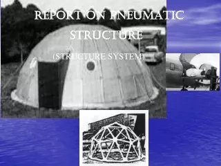
REPORT ON PNEUMATIC STRUCTURE (STRUCTURE SYSTEM) BY :- ANKITA TORO ANUSHA KULKARNI MANOJ KALAL MEGHA AKKI MEGHNA IJARI NETRAVATI K POORNIMA P B RAFIYA PARVEEN RAJEEV SINGH SHILPA J
PNEUMATIC STRUCTURES Usages in History: HISTORICAL BACKGROUND:- THE TECHNOLOGY BEHIND PNEUMATIC STRUCTURES HAS BEEN LONG KNOWN TO US. BUBBLES HAVE AROUSED PEOPLE’S CURIOSITY FOR LONG. THE MORE IMMEDIATE USE OF PNEUMATICS HOWEVER LIES IN BALOONS AND AIRSHIPS THAT HAVE GRACED OUR SKIES IN THE RECENT PAST. IN 1922, THE OASIS THEATRE IN PARIS SPORTED A PNUEMATIC HOLLOW ROOF STRUCTURE THAT WAS ROLLED INTO PLACE WHEN IT RAINED. DURING WORLD WAR PNEUMATIC STRUCTURES PLAYED AN IMPORTANT ROLE AS ‘RADOMES’, WHICH HOUSED LARGE RADAR ANTENNAE. THEY CAN CREATE ARTIFICIAL ENVIRONMENT ADAPTABLE TO HUMAN USE IN ANY PART OF THE WORLD. BUILDING WITH PNEUMATIC ROOF
PNEUMATIC STRUCTURE • ORIGIN :- • THE WORD PNEUMATIC IS DERIVED FROM THE GREEK WORD “PNEUMA”(MEANING BREATH OF AIR) ,THUS THESE ARE THE STRUCTURE WHICH ARE SUPPORTED BY AIR. • “PNEUMATIC STRUCTURE” HAS BEEN USED BY MANKIND FOR THOUSAND OF YEARS. • BUT IN THE BUILDING TECHNOLOGY IT WAS INTRODUCED ONLY ABOUT 40 YEARS AGO. • PRINCIPLE:- • ITS PRINCIPLE IS THE USE OF RELATIVELY THIN MEMBRANE SUPPORTED BY A PRESSURE DIFFERENCE. • 2) THROUGH INCREASING THE INSIDE AIR PRESSURE NOT ONLY THE DEAD WEIGHT OF THE SPACE ENVOLPE IS BALANCED, BUT THE MEMBRANE IS STRESSED TO A POINT WHERE IT CANNOT BE INDENTED BY ASYMMETRICAL LOADING . • GENERAL CHARACTERISTICS:- • 1) LIGHT WEIGHT:- • a) THE WEIGHT OF THE STRUCTURE AS COMPARED TO THE AREA IT COVERES IS VERY LESS
2) THE WEIGHT OF THE MEMBRANE ROOF , EVEN WHEN IT IS STIFFENED BY CABLES, IS VERY SMALL • 3) LOW AIR PRESSURE IS SUFFICIENT TO BALANCE IT • 4) EVEN WITH SPANS OF MORE THAN 100MTS, THE WEIGHT OF THE STRUCTURE DOES NOT EXCEED 3KG/SQUARE METRE . • SPAN :- • NO STRUCTURE CAN GURANTEE TO GIVE THE SPANS UPTO CERTAIN LIMITS CABLE STRUCTURES ARE EXCEPTIONS( CABLES FOR BRIDGES USUALLY). • FOR A BUILDING, THEN THE LIMITATION IS 500 FEET SPAN DUE TO ITS SELF WEIGHT. • ANOTHER ADVANTAGE OVER OTHER STRUCTURES IS THAT, FOR PNEUMATIC MEMBRANE , THERE IS NO THEORTICAL MAXIMUM SPAN AS DETERMINED BY STRENGTH, ELASTICITY, SPECIFIC WEIGHT OR ANY OTHER PROPERTY. • IT IS HARDLY POSSIBLE TO SPAN A DISTANCE OF OVER 36KM. WITH A STEEL CABLES AS THEY WOULD FAIL BECAUSE OF THEIR INABILITY TO SUSTAIN THEIR OWN WEIGHT. BUT WITH PNEUMATICS, SUCH SPANS ARE QUIET POSSIBLE. • 3) SAFETY:- PNEUMATIC STRUCTURES ARE SAFER THAN ANY OTHER STRUCTURE. OTHERWISE, A PROPER CARE SHOULD BE TAKEN WHILE
ESTABLISHING • ACCIDENTAL CIRCUMSTANCES ARE AVOIDED AS THEY ARE VERY LIGHT. • THERE ARE WARNING SIGNALS WHILE THE RELEASE OF RETURN VALVE. SAFETY FACTOR+ WARNING TIME IS QUIET LONG AS COMPARED TO OTHER STRUCTURES. • PNEUMATIC STRUCTURES CANT BE DESTROYED BY FIRE QUICKLY AND TOTALLY. • THEFT:- IT IS VERY SAFE NO BODY CAN OR PASS THROUGH A PNEUMATIC STRUCTURE. IF AN AIR BAG IS CUT WITH A KNIFE/ PIN, A BANG IS PRODUCED. • HUMAN HEALTH:-IN MOST CASES, PRESSURE OF NOT MORE THAN 80-100mm AND NOT LESS THAN 60mm.BUT MAN CAN WITHSTAND PRESSURES BETWEEN 0.20 ATM TO 3 ATM. THEREFORE NO HEALTH HAZARD IS PRESENTED BY CONTINOUS STAY IN A PNEUMATIC STRUCTURE. • QUICK ERECTION AND DISMANTLING:- SUITABLE FOR TEMPORARY CONSTRUCTIONS BECAUSE THEY ARE AS EASY TO DISMANTLE AS TO ESTABLISH. • 1 SQ.KM. OF AN AREA CAN BE BROUGHT DOWN IN 6 HOURS. AND ESTABLISH IN LESS THAN 10 HOURS. THE 4 HOURS DIFFERENCE IS DUE TO ESTABLISHMENT OF PEGS ETC.
6. ECONOMY:- IT IS NOT EXPENSIVE WHERE IT IS USED FOR SHIFTING STRUCTURES. FOR PERMANENT STRUCTURES, IT IS VERY EXPENSIVE. OTHERWISE THE COST PER SQURE FOOT OF AIR SUPPORTED STRUCTURES IS AMONG THE LOWEST FOR LARGE SPAN ROOFS. GOOD NATURAL LIGHT:- GIVES GOOD NATURAL LIGHT AS TRANSLUCENT/TRANSPARENT PLASTIC SHEETS ARE USED TO COVER AIR BAGS.WE CAN EVEN BRING THE WHOLE SUN INSIDE. THERE IS A LOT OF FLEXIBILITY IN GETTING SUN LIGHT(50%-80%).
TYPES OF PNEUMATIC STRUCTURES:- THESE ARE PRIMARY CLASSES OF PNEUMATIC STRUCTURES:- AIR SUPPORTED STRUCTURES AND AIR –INFLATED STRUCTURES AIR – SUPPORTED STRUCTURES:- IT CONSIST OF A SINGLE MEMBRANE(ENCLOSING A FUNCTIONALLY USEFUL SPACE) WHICH IS SUPPORTED BY A SMALL INTERNAL PRESSURE DIFFERENCE.THE INTERNALVOLUME OF A BUILDING AIR IS CONSIQUENTLY AT A PRESSURE HIGHER THAN ATMOSPHERIC. THE AIR SUPPORTED STRUCTURE USES A LOW POSITIVE PRESSURE TO SUPPORT A MEMBRANE OVER A GIVEN AREA. AIR MUST BE SUPPLIED CONTANTLY BECAUSE OF THE CONTINOUS LEAKAGE, PRIMARILY THROUGH THE BUILDINGS USED MOST OFTEN BECAUSE OF: . THEIR RELATIVELY LOW COST . THEIR SIMPLICITY OF DESIGN AND FABRICATION
AIR – INFLATED STRUCTURE:-IT IS SUPPORTED BY PRESSURIZED AIR CONTAINED WITHIN INFLATED BUILDING ELEMENT. THE INTERNAL VOLUME OF BUILDING AIR REMAINS AT ATMOSPHERIC PRESSURE. THE PRESSURIZED AIR IN THE PILLOW SERVES ONLY TO STABLIZING THE LOAD CARRYING MEMBRANE . THE COVERED SPACE IS NOT PRESSURIZED . ADVANTAGES OF AIR- INFLATED / AIR FRAME STRUTURE :- . THE ABILITY FOR SELF SUPPORT . THE POTENTIAL TO SUPPORT AN ATTACHED STRUCTURE
System Components The system components of a pneumatic structure are the envelope, pumping equipment, entrance doors, and foundation. Envelope The envelope of a pneumatic structure is a signle or double layer membrane and is made of industrial fabrics, such as fiberglass or polyester for a great stability. The material is coated with polymers in order to prevent deterioration from moisture or UV radiation. The shape of the envelope is a very important aspect in pneumatic structures; an inflated surface invlolves a double curvature which explains why most pneumatic sturctures are round. The design of the envelope depends on an evenly pressurized environment; the internal pressure must equal or exceed the external pressure to maintain a structural stability. If a pneumatic structure is not evenly pressurized, then the membrabe creats wrinkles and stress points which will lead it to fail. The envelope surface material must have high tensile strenght, resistant to weathering, tearing and fire.
Pumping Equipment The pumping equipment for an ari-inflated structure can be fans, blowers or compressors. This component is extremely important for a pneumatic structure. First of all, the internal volume of the envelope is supplied with atmospheric pressure through the pumping equipment. Secondly, the pumping equipment is used in many cases to replace any air leakage in order to maintain a stabilized pressurized environment. The amount of pressure required for a pneumatic structure depends on the weight of the material and the wind pressure. The internal pressure varies from 0.3 inAq (inches of water) for minimal inflation to a maximum of 3 inAq; or, from a minimum of 0.0111 psi to a maximum of 0.111 psi. For a dependent pneumatic structure, for instance a roof-only air supported structure, the envelope is anchored to the main structure.
Entrance Doors Access to the interior of the pneumatic structure is achieved through ordinary doors or airlocks. The most common and efficient entrance doors are the airlocks because they do not allow any air to escape from the structure minimizing the chances of having an unevenly pressurized environment. Foundation The pneumatic structures are secured on the ground using heavy weights, gound anchors or attached to a foundation. The weight of the material and the wind loads are used to determine the most appropriate anchoring system. For a small independent pneumatic structure, a ballast anchorage, blocks of concrete, or bricks can be placed around the perimeter on the seal skirt in order to stabilize the structure. For a bigger and wider pneumatic structure, reinforcing cables or nets are required to anchor and stabilize it.
CLASSIFICATION OF PNEUMATIC STRUCTURES:- PNEUMATIC STRUCTURES CAN BE FURTHER SUBDIVIDED AS:- 1)TYPE OF DIFFRENTIAL PRESSURE 2)DEGREE OF DIFFRENTIAL PRESSURE 3)TYPE OF SURFACE CURVATURE 4)PROPORTIONS • TYPE OF DIFFRENTIAL PRESSURE:-. • a) PNEUMATIC STRUCTURES USE EITHER • POSITIVE PRESSURE OR NEGATIVE PRESSURE. • b) IN (+) PRESSURE SYSTEM,THE MEMBRANE • IS ALWAYS CURVED OUTWARDS,WHEREAS IN • NEGATIVE PRESSURE SYSTEMS THE MEMBRANE IS CURVED INWARDS. • c) BEING CURVED INWARDS THERE IS A TENDENCY OF WATER LOGGING & SNOW ACCUMULATION . • d) MOREOVER,NEGATIVE PRESSURE SYSTEMS REQUIRE HIGH SUPPORTS AT THE EDGE OR IN THE CENTRE WHICH MAKES IT MORE EXPENSIVE. • e) BOTH OF THESE SYSTEMS ARE USED FOR STORAGE PURPOSES AS THEY CAN KILL THE RODENTS.
DEGREE OF DIFFERNTIAL PRESSURE:- • LOW PRESSURE SYSTEMS - • THESE SYSTEMS ARE PROVIDED WITH • LOW PRESSURE AIR ;HENCE HAVE TO • BE PROVIDED WITH CONTINUOUS SUPPLY • OFAIR.EG-AIR SUPPORTED STRUCTURES. • HIGH PRESSURE SYSTEMS - • USED FOR EASY ERECTION & DISMANTLING • ; THE PRESSURE DIFFERENCE IS B/W • 2000-7000MM OF WATER PRESSURE • (100 TO 1000 TIMES) LOW PRESSURE • SYSTEMS.THESE HIGH PRESSURE AIR • INFLATED SYSTEMS ARE EITHER HAVING • A SINGLE VALVE SYSTEM OR A DOUBLE • VALVE SYSTEMS WHICH AVOIDS IT’S • COLLAPSE.
TYPE OF SURFACE CURVATURES:- THESE STRUCTURES CAN ALSO BE CLASSIFIED ACCORDING TO THE TYPES OF CURVATURE ON THE OUTER SURFACE- • SINGLE CURVED • DOUBLY CURVED IN THE SAME DIRECTION OR SYNCLASTICS • DOUBLY CURVED IN OPPOSITE DIRECTION OR ANTICLASTIC • 4. PROPORTIONS:- ON THE BASIS OF DIFFERENT PROPORTIONS, PNEUMATIC STRUCTURES CAN BE:- • TWO DIMENSION OF SIMILAR SIZE AND ONE LARGER DIMENSION, EG:- “TUBES”,”MASTS”,”COLUMNS”,”TOWERS”. • TWO DIMENSIONS OF SIMILAR SIZE AND ONE • SMALLER DIMENSION, EG:- “CUSHIONS”,”LENSES”, • ”DISCUSS”,”MATTRESSES”. • THREE DIMENSIONS OF SIMILAR SIZE, • EG:- “BALOONS”,”BALLS”,”SPHERES”, • ”BUBBLES
MATERIALS:- ISOTROPIC:- THESE SHOW THE SAME STRENGTH AND STRETCH IN ALL DIRECTIONS. EXAMPLES ARE:- PLASTIC FILMS:- THESE ARE PRIMARILY PRODUCED FROM PVC, POLY ETHYLENE, POLYESTER, POLYAMIDE ETC. FABRICS:- THESE MAY BE MADE OF GLASS FIBRES OR SYNTHETIC FIBRES WHICH ARE COATED IN A PVC, POLYESTER OR POLYURETHENE FILM. RUBBER MEMBRANE:- THEY ARE THE LIGHTEST AND MOST FLEXIBLE. METAL FOILS:- THEY POSSESS A VERY HIGH GAS DIFFUSION RESISTANCE AND HIGH TENSILE STRENGTH . ONE OF THE MAJOR PROBLEMS IN THE USE OF METAL FOILS IS IN NEED TO PRODUCE VERY EXACT CUTTING PATTERNS
ANISOTROPIC MATERIALS:- THESE DO NOT SHOW THE SAME STRENGTH AND STRETCHABILITY IN ALL DIRECTIONS. THEY HAVE DIRECTION ORIENTED PROPERTIES. EXAMPLES ARE:- WOVEN FABRICS:- THEY HAVE TWO MAIN DIRECTION OF WEAVE. THEY CAN BE MADE OF:- . ORGANIC FIBRES EG:- WOOL,COTTON OR SILK. . MINERAL FIBRES EG:- GLASS FIBRES. . METAL FIBRES EG:- THIN STEEL WIRES. . SYNTHETIC FIBRES EG:- POLYAMIDE, POLYESTER AND POLYVINYLE. GRIDDED FABRIC:- THESE ARE COARSE-WEAVE MADE OF ORGANIC MINERAL OR SYNTHETIC FIBRES OR METALLIC NETWORKS. THEY ARE PARTICULARLY USED WHERE MAXIMUM LIGHT TRANSMISSION AND HIGH STRENGTH IS REQUIRED. SYNTHETIC RUBBERS:- COMBINATION OF PASTIC AND RUBBER. THEY CAN TAKE BETTER WEAR AND TEAR. THEY ARE LATEST AND ARE MORE RESISTANT TO ELONGATION. PLASTICS:- LIKE WOVEN FABRICS. ITS ADVANTAGE IS THAT THEY HAVE MORE OF TENSILE STRENGTH THAN NORMALLY MANUFACTURED PLASTIC SHEETS.
PNEUMATIC STRUCTURE Air supported structure: the entire internal volume of the structure is pressurized Air inflated structure: only the space between dual membranes is pressurized. The interior functional space remains at atmospheric pressure.
PROFILE CONSIDERATION Low profile structure High – Profile structure Effects of wind on a low profile structure Pressure forces due to wind can be eliminated entirely by using low profile structures and embankments
SUPPORT CONDITION In low profile structures supports carry loads that are upwardly and inwardly directed In high profile structures the loads are upwardly and outwardly directed Air inflated beam with internal pressure Pr Loaded state application of an external load tends to cause compressive stresses to develop on the upper surfaces and tension on the lower surfaces Free body diagram of left portion of beam unloaded state
PLATE FORM BEHAVIOUR Air inflated structure : an overall folding type of failure can occur in some air-inflated plates. A high internal pressure prevents this type of failure Air supported structure : air supported structures buckle differently. A local or snap through mode can occur
PUNCTURES IN AIR INFLATED STRUCTURE Due to the low internal pressures that are present, most inflated structures only gradually deflate after a puncture A structure having cells that are inflated is less likely to collapse completely than the type of structure shown in left figure Structures can be designed to be viable even if fully deflated. In the case shown the structure begins working like a suspended cable surface when deflated
MEMBRANE STRESSES General relationship pr = T1/R1 + T2/R2 For a sphere R1 = R2 =R T1 =T2 = pr R/2 Circular membrane of unit width carrying an internal pressure Pi . Tension forces in membrane T = pr R Spherical membrane carrying an internal pressure of pr