Download
1 / 36
390 likes | 524 Views
Interconnect Working Group. 2007 Edition - draft 18 July 2007 San Francisco Christopher Case Linde. ITWG Regional Chairs. Japan Hiroshi Miyazaki Masayuki Hiroi Taiwan Douglas CH Yu. US Christopher Case Robert Geffken Europe Hans-Joachim Barth Alexis Farcy. Korea

E N D
Interconnect Working Group 2007 Edition - draft 18 July 2007 San Francisco Christopher Case Linde 2007 ITRS DRAFT DO NOT PUBLISH
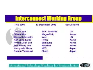
ITWG Regional Chairs Japan Hiroshi Miyazaki Masayuki Hiroi Taiwan Douglas CH Yu US Christopher Case Robert Geffken Europe Hans-Joachim Barth Alexis Farcy Korea Hyeon-Deok Lee Sibum Kim 2007 ITRS DRAFT DO NOT PUBLISH
Robert Geffken Hans-Joachim Barth Alexis Farcy Harold Hosack Paul Feeney Ken Monnig Rick Reidy Mauro Kobrinsky Hideki Shibata Kazuyoshi Ueno Michele Stucchi Susan Vitkavage Eiichi Nishimura Mandeep Bamal Quingyuan Han Robin Cheung Didier Louis Katsuhito Tokushige Masayoshi Imai Greg Smith Detlef Weber Scott Pozder Osamu Yamazaki Hiroshi Miyazaki Masayuli Hiroi Manabu Tsujimura Nohjung Kwak Hyeon Deok Lee Yuji Awano Kenichi Nishi Sibaim Kim Lucile Arnaud JD Luttmer Sitaram Arkalgud Azad Naeemi Dirk Gravesteijn NS Nagaraj Mike Mills Skip Berry Gunther Schindler Chung-Liang Chang Tomoji Nakamura Christopher Case Partial List of Contributors 2007 ITRS DRAFT DO NOT PUBLISH
Agenda • Scope, structure and 10 year synopsis • Technology requirements • Difficult challenges • Cu resistivity effects • Energy and performance • Low k roadmap • Interconnect for memory • DRAM wiring roadmap • Non-volatile interconnect requirements • Beyond metal/dielectric systems • 3D, optical and carbon nanotubes (CNT) • 3D roadmap proposal • Last words 2007 ITRS DRAFT DO NOT PUBLISH
Interconnect scope • Conductors and dielectrics • Starts at contact • Metal 1 through global levels • Includes the pre-metal dielectric (PMD) • Associated planarization • Necessary etch, strip and cleans • Embedded passives • Reliability and system and performance issues • Ends at the top wiring bond pads • “Needs” based replaced by – scaled, equivalently scaled or functional diversity drivers 2007 ITRS DRAFT DO NOT PUBLISH
Typical MPU cross section Passivation Passivation Dielectric Dielectric Wire Wire Etch Stop Layer Etch Stop Layer Via Via Dielectric Capping Layer Dielectric Capping Layer Copper Conductor with Copper Conductor with Barrier/Nucleation Layer Barrier/Nucleation Layer Global Global Intermediate Intermediate Metal 1 Metal 1 Pre Pre - - Metal Dielectric Metal Dielectric Contact Plug Metal 1 Pitch Metal 1 Pitch 2007 ITRS DRAFT DO NOT PUBLISH
Typical ASIC Chip Cross Section Passivation Wire Dielectric Global Etch Stop Layer Via Dielectric Capping Layer Copper Conductor with Barrier/Nucleation Layer Semi-Global Intermediate Metal 1 Pre Metal Dielectric Contact Plug Metal 1 Pitch 2007 ITRS DRAFT DO NOT PUBLISH
M1 Half Pitch Trends \ [nm] 2007 ITRS DRAFT DO NOT PUBLISH
Whose linewidth is it anyway? • Metal 1 design rule concerns • Staggered contacted pitch used for definition • 68 nm half pitch for 2007 • High performance MPU pitches scaling at ~0.75/2 years until 2009 • Returning to 0.7/3 years 2010 • Convergence of MPU/ASIC and DRAM pitch in 2010 • Commonality in the backend (Cu based) 2007 ITRS DRAFT DO NOT PUBLISH
Technology Requirements • Tables for HP MPU and ASIC plus DRAM • Wiring levels including “optional levels” • Reliability metrics • Minimum wiring/via pitches by level • Performance figure of merit and capacitance • Planarization requirements • Conductor resistivity with and without scattering • Barrier thickness • Dielectric metrics including effective k (UPDATED) • Crosstalk metric • Metal 1 variability due to CD and scattering • Power Index 2007 ITRS DRAFT DO NOT PUBLISH
Technology Requirements • HP MPU and DRAM tables now restated and organized as • General requirements • Resistivity • Dielectric constant • Metal levels • Reliability metrics • Power metric • Level specific requirements (M1, intermediate, global) • Geometrical • Via size and aspect ratio • Barrier/cladding thickness • Planarization specs • Variability • Materials requirements • Conductor effective resistivity and scattering effects • Electrical characteristics • Delay, capacitance, Jmax 2007 ITRS DRAFT DO NOT PUBLISH
+ 4 Elements + 45 Elements(Potential) 12 Elements The March of Materials 2007 ITRS DRAFT DO NOT PUBLISH
Difficult challenges (1 of 3) • Meeting the requirements of scaled metal/dielectric systems • Managing RC delay and power • New dielectrics (including air gap) • Controlling conductivity (liners and scattering) • Filling small features • Liners • Conductor deposition • Reliability • Electrical and thermo-mechanical • Engineering a manufacturable interconnect stack compatible with new materials and processes • Defects • Metrology • Variability 2007 ITRS DRAFT DO NOT PUBLISH
Difficult challenges (2 of 3) • Meeting the requirements with equivalent scaling • Interconnect design and architecture (includes mulit-core benefits) • Alternative metal/dielectric assemblies • 3D with TSV • Interconnects beyond metal/dielectrics • 3D • Optical wiring • CNT • Reliability • Electrical and thermo-mechanical • Engineering a CMOS-compatible manufacturable interconnect system • Non-traditional materials (for optical, CNT etc.) • Unique metrology (alignment, chirality measurements, turning radius etc) 2007 ITRS DRAFT DO NOT PUBLISH
Difficult challenges (3 of 3) • Adding functional diversity • Mixed technologies • Si, GaAs, HgCdTe together • Mixed signalling approaches • Rf • Passive devices • Intelligent Interconnect (active devices, sensors, MEMS, biochips, fluidics, etc. in interconnect) • Repeaters in interconnect, combined metallic/semiconducting CNT interconnects • Back-end memory • Variable resistor via • Reliability • Electrical and thermo-mechanical • Engineering a CMOS-compatible manufacturable interconnect system • Non-traditional materials III/V, II/VI • Deposition (low temperature epi) • Unique metrology (composition) 2007 ITRS DRAFT DO NOT PUBLISH
Size matters • 2003 – the impending impact of Cu resistivity increases at reduced feature sizes (due to scattering) - first noted • 2004 – metrics introduced to highlight the impact of width dependent scattering on the effective resistivity and impact on RC delay • Models have been refined to more accurately predict the resistivity due to changes in aspect ratio, shape and metal thickness • 2007 - Metrics updated – managed architecture • Adapt the same methodology for DRAM when Cu is introduced (2007) 2007 ITRS DRAFT DO NOT PUBLISH
Size matters Figure From Infineon 2007 ITRS DRAFT DO NOT PUBLISH
Dynamic Power • Increasing concern about rising dynamic power in the interconnect stack • Interconnects make a significant contribution to total dynamic power • Impacts effective k roadmap • Drives reduction in parasitic capacitance • Dynamic power is a key constraint for high performance MPUs • Alternative interconnect technologies (optical, CNT, RF, etc.) should be performance competitive in terms of delay and power • Influence of number of functions (N), activity (A) and frequency (F): P = (NAF)CV2 2007 ITRS DRAFT DO NOT PUBLISH
M1IntermediateGlobal upper value P (W/GHz-cm2) C (pF/cm) lower value Used lowest expected k value 90 65 45 32 22 16 M1 ½ pitch 90 65 45 32 22 16 M1 ½ pitch Capacitance and Power Index 2007 ITRS DRAFT DO NOT PUBLISH
R and C variability w=80nm t =70nm w=80nm t =150nm w=100nm t =200nm w=250nm t =200nm 2007 ITRS DRAFT DO NOT PUBLISH
Integration Schemes 2007 ITRS DRAFT DO NOT PUBLISH
Low-k update 2007 ITRS DRAFT DO NOT PUBLISH
Low-k Trend (2003-2006 IITC, IEDM, VL, AMC) 2007 ITRS DRAFT DO NOT PUBLISH
Low-k Roadmap Table Update 2007 ITRS DRAFT DO NOT PUBLISH
DRAM Small changes in specific via and contact resistivity Contact A/R (stacked capacitor) rises to >20 in 2010 - a nearby red challenge - associated with the 45 nm DRAM half pitch Cu implemented in 2007 Low k with an effective dielectric constant of 3.1 – 3.4 pushed back one year to 2009 Plan to distinguish embedded, flash, and traditional DRAM along with alternative memory in the interconnect in the future (2009) 2007 ITRS DRAFT DO NOT PUBLISH
2007 DRAM Table - n+Si, p+Si and Via 1. Values for Contact and Vias are basically consistent with measured data up to 2009 2. Beyond 2009 the values are extrapolated as proposed previously by Japan TWG: Based on contact CD scaling assumption, 30 % every 2 years (factor = 0,83/year) is between compensation of width scaling (factor = 0,89/year) and area scaling (factor = 0,79/year); 30 % every 2 years is a good approach to keep the contact Rs below a certain limit. 3. Values 2010 to 2022 should stay in red Calculated values by using the scaling factor of 0.83 2007 ITRS DRAFT DO NOT PUBLISH
Jmax 2007 – small changes 2007 ITRS DRAFT DO NOT PUBLISH
IO - Memory IF & Chip-to-Chip IF - Main Processor DPE DPE DPE DPE DPE DPE DPE DPE Main Processor DPE DPE DPE DPE DPE DPE DPE DPE Multi-core Impact on Interconnect • Wiring lengths change • Critical path reduced (in core) • Mechanical integrity challenges will change • Jmax changes • Hierarchical structure may no longer be necessary • Converge to more fine pitch local/intermediate wires • Power and ground delivered through grid • Global delay challenge relaxed • 3D may include multi-core • Need to consider splitting metrics into: • In-core (intra-tile) and Inter-core (inter-tile) • New bandwidth requirements Figure From ITRS 2006 Design TWG 2007 ITRS DRAFT DO NOT PUBLISH
Emerging Interconnect • Use geometry • 3D • Air gap • Use different signaling methods • Signal design • Signal coding techniques • Use innovative design and package options • Interconnect - centric design • Package intermediated interconnect • Chip-package co-design Figure From Stanford 2007 ITRS DRAFT DO NOT PUBLISH
From low k to no k - air gaps • Introduction of air gap architectures • Creation of air gaps with non-conformal deposition • Removal of sacrificial materials after multi-level interconnects • Values of effective k-value down to 1.7 with low crosstalk levels • Localized air gaps to maintain good thermal and mechanical properties Ultra-low kand Air gap (k<1.7) (CVD and Spin-on) 2007 ITRS DRAFT DO NOT PUBLISH
Emerging interconnect • Use different physics • Optics (waveguides, emitters, detectors, free space, trans-impedance amps, modulators) • RF/microwaves (transmitters, receivers, free space, waveguides) • Terahertz photonics • Radical solutions • Nanowires/nanotubes • Molecules • Spintronics • Quantum wave functions 2007 ITRS DRAFT DO NOT PUBLISH
Hypothetical On-die Optical Interconnects with WDM 2007 ITRS DRAFT DO NOT PUBLISH
High Density 3D Integration • Through silicon via (TSV) • Reliability • Physical metrics (pitch, diameter, density) • Alignment tolerance • Bond layer • Reliability • Interfacial defect density • Adhesion • List of “Difficult Challenges”, e.g. TSV processes, alignment, low k impact on TSV, etc. 2007 ITRS DRAFT DO NOT PUBLISH
H Hedler 2007 ITRS DRAFT DO NOT PUBLISH
Summary of Notable 2007 changes • Low-k slowdown • New range for bulk k and keff • New Technology Introduction • ALD barrier processes and metal capping layers for Cu are lagging in introduction. • No solutions seen for Cu resistivity rise • Power Metric • Capacitance per unit length decreases due to decreases of the dielectric constant. • However, the dynamic power is expected to increase because of the increased number of metallization layer, larger chip size and increased frequency. 2007 ITRS DRAFT DO NOT PUBLISH
Last words • Must manage the power envelope • Must continue to meet requirements of scaled metal/dielectric systems while developing CMOS-compatible equivalent scaling solutions • Cu resistivity impact real but manageable • materials solutions alone cannot deliver performance - end of traditional scaling • integrated system approach required • Functional diversity enhances value 2007 ITRS DRAFT DO NOT PUBLISH