Download
1 / 14
140 likes | 159 Views
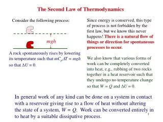
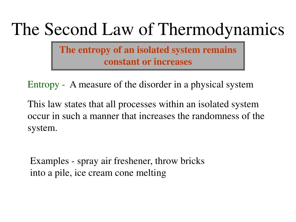
The Second Law of Thermodynamics. The entropy of an isolated system remains constant or increases. Entropy -. A measure of the disorder in a physical system. This law states that all processes within an isolated system occur in such a manner that increases the randomness of the system.

E N D
The Second Law of Thermodynamics The entropy of an isolated system remains constant or increases Entropy - A measure of the disorder in a physical system This law states that all processes within an isolated system occur in such a manner that increases the randomness of the system. Examples - spray air freshener, throw bricks into a pile, ice cream cone melting
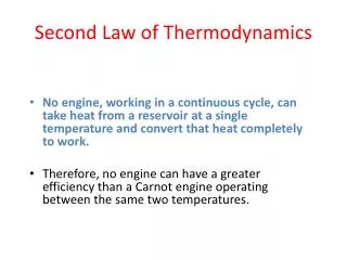
Consequences of the Second Law of Thermodynamics • Heat will never flow spontaneously from a cold body to a hot body. • You cannot construct an engine that does nothing but convert heat to useful work. • Every isolated system becomes more disordered over time.
Heat Engines A heat engine uses energy provided in the form of heat to do work and then exhausts the heat which cannot be used to do work. Heat engines such as automobile engines operate in a cyclic manner, adding energy in the form of heat in one part of the cycle and using that energy to do useful work in another part of the cycle.
Heat engines are typically illustrated on a pV - diagram For a cyclic heat engine process, the PV diagram will be closed loop. The PV diagram provides the framework for the analysis of any heat engine which uses a gas as a working substance.
Terms • Adiabatic – no heat added or removed • Isothermal – no change in temperature • Isochoric – no change in volume • Isobaric – no change in pressure Q = 0 U = 0 W = 0
An ideal monatomic gas is taken through the cycle ABCA as shown. At A, the temperature of the gas is 400 K. Determine: (a) The temperature of the gas at B, and C. (b) The work done on or by the gas during each process (AB, BC, CA).(c) The net output work for the entire cycle.(d) The heat added or removed during each process (AB, BC, CA).(e) The heat added or removed for the entire cycle.(f) The change in internal energy for each process (AB, BC, CA).(g) The change in internal energy for the entire cycle. Using the temperature @ A and PV = nRT, we can determine the number of mols of gas 3000 A 2000 P (Pa) PV = nRT 1000 B (2500)2 = n(8.31)(400) C 2 4 6 n = 1.5 mols V(m3)
Using the combined gas law, we can determine • the temperature @ B, and C. TB= 260 K PA VA PB VB ____________ ____________ = TA TB 5000(TB)= 1,300,000 2500(2)(500)(6.5) ____________ ____________ = Cross multiply to solve 400TB Repeat for Tc 5000(Tc)= 400,000 2500(2)(500)(2) ____________ ____________ = 400Tc TC= 80 K
(b) Using W = – PV we can determine the work for each process 3000 2000 P (Pa) Pressure goes from 2500 Pa to 500 Pa, thus the average pressure is 1500 Pa AB 1000 V = Vf - Vi V = 6.5 – 2 = 4.5 m3 2 4 6 V(m3) W = – (1500) (4.5) = - 6750 J Pressure stays constant at 500 Pa, thus the average pressure is 500 Pa BC Pressure goes from 500 Pa to 2500 Pa, thus the average pressure is 1500 Pa CA V = Vf - Vi V = Vf - Vi V = 6.5 – 6.5 = 0 V = 2 – 6.5 = - 4.5 m3 W = – (1500) (0) = 0 J W = – (500) (- 4.5) = + 2250 J
3000 TA = 400 K n = 1.5 mols 2000 P (Pa) Q for AB is not Cp or Cv 1000 TB = 260 K Cannot solve for Q for AB yet TC= 80 K 2 4 6 V(m3) (d) using Q = nCpT we can determine the heat for BC using Q = nCvT we can determine the heat for CA Q = nCpT Q = nCvT BC CA Q = (1.5)(20.775)(80 – 260) Q = (1.5)(12.465)(400 – 80) Q = - 5610 J Q = + 5980 J
3000 TA = 400 K (f) using U = 3/2nRT we can determine the change in internal energy for each process. n = 1.5 mols 2000 P (Pa) 1000 TB = 260 K TC= 80 K 2 4 6 U = 3/2nRT AB V(m3) U = (3/2)(1.5)(8.31)(260 - 400) U = - 2620 J U = 3/2nRT U = 3/2nRT BC CA U = (3/2)(1.5)(8.31)(80 - 260) U = (3/2)(1.5)(8.31)(400 - 80) U = - 3360J U = + 5980 J
Put what we know into a table - 6750 J + 2250 J + 0 J - 4500 J + 4500 J +4130 J - 5610 J + 5980 J -2620 J - 3360 J + 5980 J 0 J add across to determine the net (c), (e), and (g) use U = Q + W to determine the missing info This is always true for the entire cycle (U = 0) because it starts and ends at the same T!
Efficiency • The efficiency of anything is a quantitative measure of how well it does what it is supposed to do. • Thus for a heat engine . . . . . . . . . Where W = work done and QH = heat input
applying energy conservation QH = W + QL Where W = work done, QH = heat input, and QL = exhaust heat Thus . . . .
maximum (Carnot) thermal efficiency Carnot's Assumption: Heat cannot be taken in at a certain temperature and converted to work with no other change in the system of surroundings , if we ignore these changes, we can calculate the maximum efficiency Thus . . . . Where TH = high temperature, and TL = low temperature* *T must be in Kelvin