LVDT Transducer
1.99k likes | 7.06k Views
Instrumentation 2 Displacement Transducers Higher Certificate in Technology (Manufacturing Technology). LVDT Transducer. LVDT or Linear Variable Differential Transformer is a non-contact transducer that converts linear displacement into an analog electrical output signal.

LVDT Transducer
E N D
Presentation Transcript
Instrumentation 2 Displacement TransducersHigher Certificate in Technology (Manufacturing Technology)
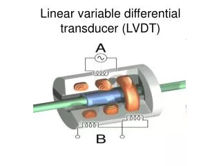
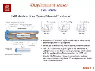
LVDT Transducer • LVDT or Linear Variable Differential Transformer is a non-contact transducer that converts linear displacement into an analog electrical output signal. • LVDTs consist of primary transformer coils wound on non-magnetic cylindrical-coil forms. • Two secondary transformer coils are wound on top of the primary. This coil assembly is then installed in a mechanical housing. • The other major component is a ferromagnetic core moving inside the coil form
LVDT Transducer-Operation • In operation, the primary coil typically is excited at 5- to 8-V AC between 60 Hz and 20 kHz • The alternating current in the primary winding creates an axial magnetic flux field that is concentrated in the core • This flux is coupled to the secondary windings through the core, inducing an output voltage in each secondary winding
LVDT Transducer-Operation • When the core is centered between the two secondary windings the voltage induced in each is identical • Voltage Va induced in secondary a and voltage Vb induced in secondary b will be in phases with the excitation voltage - the output (VaVb) will be zero • The core position where the output voltage is zero is referred to as the null position
LVDT Transducer-Operation • When the core, or armature, is moved in either direction from the null position, the amplitude of VaVb changes in direct proportion to the displacement. The phase relationships with the excitation also changes • In one direction, the output signal will be in phase with the excitation and 180° out of phase in the other direction.
LVDT Transducer-Features • The output voltage, therefore, has two components: - amplitude indicating the magnitude of the displacement, and - phase relationship indicating direction of displacement • There is no electrical contact across the transducer position sensing element which for the user of the sensor means clean data, infinite resolution and a very long life • LVDT linear position sensors are readily available that can measure movements as small as a few millionths of an inch up to several inches, but are also capable of measuring positions up to ±20 inches (±0.5 m)
Ultrasonic Transducer • An ultrasonic transducer is a device that converts energy into ultrasound or sound waves above the normal range of hearing for humans • Piezoelectric crystals have the property of changing size when an electric voltage is applied • Thus applying an alternating voltage (AC) can cause them to oscillate at very high frequencies producing very high frequency sound waves • Since piezoelectric crystals generate a voltage when force is applied to them the same crystal can be used as an ultrasonic detector • Alternative methods for creating and detecting ultrasound include magnetostriction and capacitive actuation • Ultrasonic transducers are used in many applications including burglar alarms, and non-destructive testing.
Industrial Ultrasound • Example - Non-destructive testing of a swing shaft showing spline cracking • Frequencies of 2 to 10 MHz are common but for special purposes other frequencies are used • Inspection may be manual or automated and is an essential part of modern manufacturing processes • Most metals can be inspected as well as plastics and aerospace composites • Lower frequency ultrasound (50 kHz to 500 kHz) can also be used to inspect less dense materials such as wood, concrete and cement
Ultrasonic range finding • A common use of ultrasound is in range finding; this use is also called sonar • An ultrasonic pulse is generated in a particular direction. If there is an object in the path of this pulse, part or all of the pulse will be reflected back to the sender as an echo and can be detected • By measuring the difference in time between the pulse being transmitted and the echo being received, it is possible to determine how far away the object is. • Although range finding underwater is performed at both sub-audible and audible frequencies for great distances (1000 to 30000 meters), ultrasonic range finding is used when distances are shorter and the accuracy of the distance measurement is desired to be finer • Ultrasonic measurements may be limited from about a hundred to a thousand meters, but can be performed with one-centimeter to one-meter accuracy.
Proximity Detectors • Proximity detectors are electrical or electronic sensors that respond to the presence of a material • Three major types are inductive, magnetic and capacitive • Inductive and magnetic sensors require material to be monitored to be metallic while capacitive type can monitor all materials
Proximity Detectors-Types • In the inductive transducer element, the inductance of the element is changed by the proximity of metal materials • In the magnetic transducer element, the magnetic field is changed by the presence of metal materials • In the capacitive transducer element , the capacitance of the transducer element can be changed by the presence of non-metallic materials
Proximity Detectors-Detection Features • In transducer applications, it is the nearness of the material to the transducer that allows the change in electrical or electronic function to take place • Some typical proximity distances for metallic materials are shown in figure A, while some typical proximity distances for non-metallic materials are shown in figure B
Proximity Detectors-Features • Proximity detectors have no moving parts and so do not wear out from constant use • They do not contact the material so are not destroyed by the material and the material itself is not marred • Proximity sensors can detect small, lightweight parts and can detect metal through paint and other coverings • They can detect irregular shaped objects regardless of the direction of entry into the sensing field • Control functions are possible at electronic speeds
Proximity Detectors-Inductive • An inductive sensor undergoes an inductive change owing to the proximity of the material • This is usually accomplished by the inductance ratio of a pair of coils in the sensor • Other inductive sensors project a very low level inductive field in front of the sensor • As a conductive material enters the field, eddy currents are generated in the material that reduces the impedance of the sensor
Proximity Detectors-Inductive Sensor Operating Points • The operating point of the inductive sensor is different for all materials and indeed all sensors • Each manufacturer provides a curve that describes how much of the sensor must be covered to produce an output signal
Proximity Detectors-Inductive Sensor Operating Points Verses Sensing Distances • In this example, a steel target whose sensing distance is 8mm must cover 16mm of the sensor in order to begin operating
Proximity Detectors-Inductive Sensor Operating Points Scale Factor • Each sensor has a material scale factor • The scale factors are determined by the sensor manufacturer • Example set of scale factors are shown • To determine sensing distance for other metals using the same sensor, simply multiply the sensing distance for steel times the scale factor • Example: 8mm x 0.3 = 2.4mm • If copper covered 16mm of the sensor, it would be detected at 2.4mm
Proximity Detectors-Inductive Sensor Applications • A typical inductive sensor is the Rechner IAS 20 • This Sensor operates on 10-30 volts DC • Up to six of these sensors can be operated in series or parallel to perform logic functions • Flush mounted sensors have a detection field that extends in front of the sensor head • The field does not extend beyond the side of the sensor • This allows for the detection of closely spaced items
Proximity Detectors-Inductive Sensor Applications • Example - Web break detection can be accomplished with inductive sensors • As the reel of metallic mesh passes the sensor, the sensor detects a constant flow • If there is a break in the mesh, the output of the sensor will change • Example – A contactless cam switch can be made using the sensor • Since the field strength and repeatability of the switch point is accurately controlled, the sensor can be made to detect only the high point of the cam and drop out on the low part of the cam
Proximity Detectors-Capacitive • An capacitive sensor undergoes an capacitive change owing to the proximity of the material • As a material enters the field, the sensors ability to detect it is dependent on the dielectric property of the target material • Each sensor is constructed to have a range of dielectric materials that it will detect
Proximity Detectors-Capacitive Sensor Operating Points • The operating point of the capacitive sensor is different for all materials and indeed all sensors • Each manufacturer provides a curve that describes how much of the sensor must be covered to produce an output signal
Proximity Detectors-Capacitive Sensor Operating Points Verses Sensing Distances • In this example, a steel target whose sensing distance is 8mm must cover 16mm of the sensor in order to begin operating
Proximity Detectors-Capacitive Sensor Operating Points Scale Factor • Each sensor has a material scale factor • The scale factors are determined by the sensor manufacturer • Example set of scale factors are shown • To determine sensing distance for other materials using the same sensor, simply multiply the sensing distance for steel (or water) times the scale factor • Example: 8mm x 0.4 = 3.2mm • If PVC covered 16mm of the sensor, it would be detected at 3.2mm
Proximity Detectors-Capacitive Sensor Applications • A typical capacitive sensor is the Rechner IAS 70 • This sensor operates on 10-30 volts DC • Up to six of these sensors can be operated in series or parallel to perform logic functions • Two types of sensors are available-flush mount and non-flush mount
Proximity Detectors-Capacitive Sensor Applications • Flush-mount sensors can be mounted side by side to cover a large area • Can be used to sense a large block of material • Non flush mount sensor can be used to detect powder or liquid • Can be used as level indicators
Proximity Detectors-Magnetic • A coil situated in a magnetic field will have a current induced in it if the magnetic flux changes • The magnitude of the induced current will depend on the rate at which the flux is changed • A coil is wound around a bar magnet and one pole of the magnet is located close to the ferrous object • If the object moves the flux in the magnet changes and a current is induced in the coil
Proximity Detectors-MagneticFactors affecting sensor output • The speed at which the magnetic flux is interrupted is directly proportional to the speed of passage of the object past the sensor • It is attenuated by coil and iron losses which predominate at high frequencies • Output amplitude is inversely proportional to the distance between object and sensor • In general, the output is greater for a greater mass of moving ferrous material
References • http://en.wikipedia.org/wiki/LVDT • http://en.wikipedia.org/wiki/Magnetoresistance • http://en.wikipedia.org/wiki/Ultrasonic_transducer • http://en.wikipedia.org/wiki/Ultrasound • http://en.wikipedia.org/wiki/Giant_magnetoresistive_effect • http://www.rdpe.com/displacement/lvdt/lvdt-principles.htm • http://www.macrosensors.com/lvdt_macro_sensors/lvdt_tutorial/lvdt_primer.pdf • http://www.hydraulicspneumatics.com/200/FPE/Sensors/Article/True/6440/Sensors