MOS Capacitors
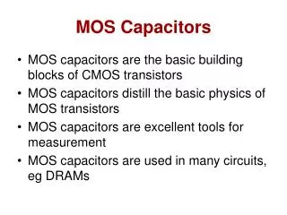
MOS Capacitors. MOS capacitors are the basic building blocks of CMOS transistors MOS capacitors distill the basic physics of MOS transistors MOS capacitors are excellent tools for measurement MOS capacitors are used in many circuits, eg DRAMs. MOS Capacitors.

MOS Capacitors
E N D
Presentation Transcript
MOS Capacitors • MOS capacitors are the basic building blocks of CMOS transistors • MOS capacitors distill the basic physics of MOS transistors • MOS capacitors are excellent tools for measurement • MOS capacitors are used in many circuits, eg DRAMs
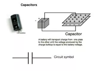
MOS Capacitors • Metal” can be metal, or more frequently heavily doped poly-Si • “Oxide” is usually silicon dioxide, but can be some other high k dielectric • “Semiconductor” is usually Si , but can be SiGe, SiC
Band-bending in a p-type Semiconductor (cont’d) • At inversion Surface potential ψs =2φB ~ 0.7- 0.8 V • Threshold voltage: Gate Voltage required to just produce inversion VT = 2φB ++ VFB ~ 0.3 - 1.0 V
MOS C-V Plot Cox = Oxide Capacitance = ox / dox CD = Depletion Capacitance = s / xD xD = Depletion width in Si = (2s s / q Na)
MOS Transistors • To the MOS capacitor, a source and drain are added. • The MOS transistor is a four terminal device Source (S), Drain (D), Gate (G) and Body or Substrate (B). • When VGS > VT, an inversion layer is formed which is a conducting channel between S and D. This channel allows drain current ID to flow between S and D.
MOS Transistor Output Characteristics Salient Features of the Output Characteristics • Input is a voltage : VGS • ID is constant (independent of VDS) in saturation • ID varies non-linearly with input VGS {goes as (VGS − VT)2 in saturation} • All curves pass through the origin • Input current is almost zero (fA – pA)
MOS Transistor Subthreshold Characteristics Subthreshold swing ~ 60 - 100 mV/decade
Body Effect • If the body or substrate is not connected to source ( as it normally would be), the “body effect” comes into play • VT is increased due to larger depletion regions in the substrate, and larger charges that need to be supported VT – V0 = K(VBS)1/2
GATE DRAIN SOURCE BODY Modern VLSI Transistors: Scaling
MOS Transistor Modeling • Modeling is important because we need equations or circuit models to put into circuit simulators of circuit diagrams • Large-signal (for digital) and small-signal (for analog) models • Models tend to be very complex, but must yet be “compact”
MOS Transistor Modeling Large Signal Models • Many large-signal models exist, eg • SPICE Levels 1,2,3 • BSIM versions 2,3,4 • EKV • Basic current equations used are similar to the equations derived, with many fitting parameters
Advantages of Scaling • More transistors per chip (1/k2) • Improvement in speed - due to decreasing L, and hence due to decreasing transit times - due to increasing current and hence improved parasitic capacitance charging time • Improved “throughput” of the chip • Note that vertical dimensions (oxide thickness, junction depths) also have to be scaled
Scaling Contd.. • W=0.7, L=0.7, Tox=0.7 • => Lateral and vertical dimensions reduce 30 % • Area Cap = C = 0.7 X 0.7 = 0.7 • 0.7 • => Capacitance reduces by 30 % • Die Area = X x Y = 0.7x0.7 = 0.72 • => Die area reduces by 50 % • Vdd=0.7, Vt=0.7, T ox=0.7, I=(W/L) (Cox)(V-Vt)2 = 0.7 • T= C x Vdd = 0.7, Power = CV2f = 0.7 x 0.72 = 0.72 • I 0.7 • => Delay reduces by 30 % and Power reduces by 50 %
Disadvantages of Scaling • Short Channel effects • Complex technology • Parasitic effects dominate over transistor effects • High static power dissipation
Limits to Scaling • Lithography • Quantum effects • Oxide tunneling
Short Channel Effects • VT roll-off due to charge sharing • Drain induced barrier lowering (DIBL) • Hot-carrier effects • Latch-up
Effect of DIBL on MOS Characteristics VT = VT0 − VDS is the DIBL factor
Velocity Saturation Effects • For long-channel transistors, the lateral electric field E is small, so velocity of electrons is given by v = E (Ohm’s Law) • For short-channel transistors, E becomes large, and velocity saturates to vsat • For short-channel transistors, current ID is less than that predicted by the long-channel model • Saturation can be due to velocity saturation, not pinchoff; Isat = Cox vsat W (VGS− VT)
Lightly-doped Drain (LDD) • LDD reduces E and therefore hot carrier effects
Conclusions • MOS transistors are conceptually simple devices • Both NMOS and PMOS transistors can be made, and effectively combined in CMOS circuits • Transistor scaling leads to great benefits, and has driven Moore’s law during the last three decades • Transistor down-scaling leads to some problems, which have been effectively combated by improved transistor design • Scaling is likely to continue till at least 2010, when transistor dimensions will be less than 0.05μm