Download
1 / 33
330 likes | 369 Views
Learn about digital and analog modulation, frequency division, and modulation schemes for effective wireless data transmission in mobile communications. Study advanced techniques like Minimum Shift Keying (MSK) and Quadrature Amplitude Modulation (QAM).

E N D
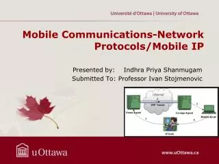
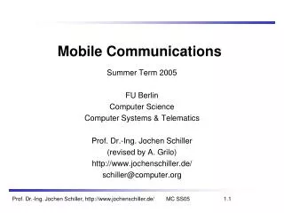
Mobile Communications Instructor M. Naman Chaudhary MS(Multimedia and Communication) Muhammad Ali Jinnah University Islamabad Campus
Wireless Transmission CH = 2 Mobile Communications JOCHEN SCHILLER 2nd Edition
Modulation • Digital modulation • digital data (0 and 1) is translated into an analog signal (base band) • Required if digital data has to be transmitted over a media that only allows for analog transmission - old analog telephone system and wireless networks • differences in spectral efficiency, power efficiency, robustness • Analog modulation • shifts center frequency of baseband signal up to the radio carrier • Motivation • smaller antennas (e.g., /4, 1 MHz over 1.8 GHz) • Frequency Division Multiplexing • medium characteristics: long waves for submarines, short waves for handheld devices, very short waves for directed microwave transmission • Basic schemes • Amplitude Modulation (AM) • Frequency Modulation (FM) • Phase Modulation (PM)
Modulation and demodulation analog baseband signal digital data digital modulation analog modulation radio transmitter 101101001 radio carrier analog baseband signal digital data analog demodulation synchronization decision radio receiver 101101001 radio carrier
Digital modulation 1 0 1 • Modulation of digital signals known as Shift Keying • Amplitude Shift Keying (ASK): • very simple • low bandwidth requirements • very susceptible to interference • Frequency Shift Keying (FSK): • needs larger bandwidth • Phase Shift Keying (PSK): • more complex • robust against interference t 1 0 1 t 1 0 1 t
Advanced Frequency Shift Keying • bandwidth needed for FSK depends on the distance between the carrier frequencies • special pre-computation avoids sudden phase shifts MSK (Minimum Shift Keying) • bit separated into even and odd bits, the duration of each bit is doubled • depending on the bit values (even, odd) the higher or lower frequency, original or inverted is chosen • the frequency of one carrier is twice the frequency of the other • Equivalent to offset QPSK • even higher bandwidth efficiency using a Gaussian low-pass filter GMSK (Gaussian MSK), used in GSM
Example of MSK 0 1 1 0 1 0 1 bit data even 0 1 0 1 even bits odd 0 0 1 1 signal h n n hvalue - - + + odd bits low frequency h: high frequency n: low frequency +: original signal -: inverted signal highfrequency MSK signal t No phase shifts!
Q I 1 0 Q 11 10 I 00 01 Advanced Phase Shift Keying • BPSK (Binary Phase Shift Keying): • bit value 0: sine wave • bit value 1: inverted sine wave • very simple PSK • low spectral efficiency • robust, used e.g. in satellite systems • QPSK (Quadrature Phase Shift Keying): • 2 bits coded as one symbol • symbol determines shift of sine wave • needs less bandwidth compared to BPSK • more complex • Often also transmission of relative, not absolute phase shift: DQPSK - Differential QPSK (IS-136, PHS) A t 01 11 10 00
Quadrature Amplitude Modulation • Quadrature Amplitude Modulation (QAM): combines amplitude and phase modulation • it is possible to code n bits using one symbol • 2n discrete levels, n=2 identical to QPSK • bit error rate increases with n, but less errors compared to comparable PSK schemes Example: 16-QAM (4 bits = 1 symbol) • Symbols 0011 and 0001 have the same phase φ, but different amplitude a. 0000 and 1000 have different phase, but same amplitude. • used in standard 9600 bit/s modems Q 0010 0001 0011 0000 φ I a 1000
Hierarchical Modulation • DVB-T modulates two separate data streams onto a single DVB-T stream • High Priority (HP) embedded within a Low Priority (LP) stream • Multi-carrier modulation • splitting data into several components, and sending each of these components over separate carrier signals (about 2000 or 8000 carriers) • QPSK, 16 QAM, 64QAM • Example: 64QAM • good reception: resolve the entire 64QAM constellation • poor reception, mobile reception: resolve only QPSK portion • 6 bit per QAM symbol, 2 most significant determine QPSK • HP service coded in QPSK (2 bit), LP uses remaining 4 bit • HP for the standard resolution • LP for the high resolution Q 10 I 00 000010 010101
Antennas: isotropic radiator • Radiation and reception of electromagnetic waves, coupling of wires to space for radio transmission • Isotropic radiator: equal radiation in all directions (three dimensional) - only a theoretical reference antenna • Real antennas always have directive effects (vertically and/or horizontally) • Radiation pattern: measurement of radiation around an antenna z y z ideal isotropic radiator y x x
Antennas: simple dipoles • Real antennas are not isotropic radiators but, e.g., dipoles with lengths /4 on car roofs or /2 as Hertzian dipole • Example: Radiation pattern of a simple Hertzian dipole • Gain: maximum power in the direction of the main lobe compared to the power of an isotropic radiator (with the same average power) /4 /2 y y z simple dipole x z x side view (xy-plane) side view (yz-plane) top view (xz-plane)
Antennas: directed and sectorized • Often used for microwave connections or base stations for mobile phones (e.g., radio coverage of a valley) y y z directed antenna x z x side view (xy-plane) side view (yz-plane) top view (xz-plane) z z sectorized antenna x x top view, 3 sector top view, 6 sector
Antennas: diversity • Grouping of 2 or more antennas • multi-element antenna arrays • Antenna diversity • switched diversity, selection diversity • receiver chooses antenna with largest output • diversity combining • combine output power to produce gain • Co-phasing needed to avoid cancellation /2 /2 /4 /2 /4 /2 + + ground plane
Signal propagation ranges • Transmission range • communication possible • low error rate • Detection range • detection of the signal possible • no communication possible • Interference range • signal may not be detected • signal adds to the background noise sender transmission distance detection interference
Propagation in free space always like light (straight line) Receiving power proportional to 1/d² (d = distance between sender and receiver) Receiving power additionally influenced by fading (frequency dependent) shadowing reflection at large obstacles refraction depending on the density of a medium scattering at small obstacles diffraction at edges Wave Propagation Ground Waves(<2MHz) Sky Waves (<30 MHz) Line of Sight(>30MHz) Signal propagation refraction shadowing reflection scattering diffraction
Spread Spectrum Transmitter Input is fed into a channel encoder • Produces analog signal with narrow bandwidth • Signal is further modulated using sequence of digits • Spreading code or spreading sequence • Generated by pseudonoise, or pseudo-random number generator • Effect of modulation is to increase bandwidth of signal to be transmitted On receiving end, digit sequence is used to demodulate the spread spectrum signal • Signal is fed into a channel decoder to recover data
Spread Spectrum • What can be gained from apparent waste of spectrum? • Immunity from various kinds of noise and multipath distortion • Can be used for hiding and encrypting signals • Several users can independently use the same higher bandwidth with very little interference
Frequency Hoping Spread Spectrum (FHSS) • Signal is broadcast over seemingly random series of radio frequencies • A number of channels allocated for the FH signal • Width of each channel corresponds to bandwidth of input signal • Signal hops from frequency to frequency at fixed intervals • Transmitter operates in one channel at a time • Bits are transmitted using some encoding scheme • At each successive interval, a new carrier frequency is selected
Frequency Hoping Spread Spectrum • Channel sequence dictated by spreading code • Receiver, hopping between frequencies in synchronization with transmitter, picks up message • Advantages • Eavesdroppers hear only unintelligible blips • Attempts to jam signal on one frequency succeed only at knocking out a few bits
DSSS (Direct Sequence Spread Spectrum) • XOR of the signal with pseudo-random number (chipping sequence) • many chips per bit (e.g., 128) result in higher bandwidth of the signal
Next Week Lecture Plan Telecommunication Systems CH = 4 Mobile Communications by JOCHEN SCHILLER
Uploaded by Ahmad Mushtaq www.AhmadMushtaq.com Student at Department of Information Technology, Bahauddin Zakariya University, Multan, Pakistan