Download
1 / 32
320 likes | 414 Views
The Development of Fluidised Powder Target Technology for a Neutrino Factory or Muon Collider. Ottone Caretta, Chris Densham, Peter Loveridge Rutherford Appleton Laboratory 22 September 2010. Looking for the ‘Goldilocks’ target technology. LIQUIDS. SOLIDS. Segmented Pebble bed.

E N D
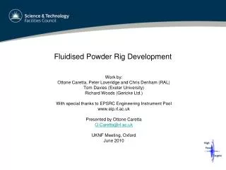
The Development of Fluidised Powder Target Technology for a Neutrino Factory or Muon Collider Ottone Caretta, Chris Densham, Peter Loveridge Rutherford Appleton Laboratory 22 September 2010
Looking for the ‘Goldilocks’ target technology LIQUIDS SOLIDS Segmented Pebble bed Contained liquids Open jets Monolithic Moving Too bendy?
Looking for the ‘Goldilocks’ target technology LIQUIDS SOLIDS Segmented Pebble bed Contained liquids Open jets Monolithic Moving Too bendy? Too complicated?
Looking for the ‘Goldilocks’ target technology LIQUIDS SOLIDS Segmented Pebble bed Contained liquids Open jets Monolithic Moving Too cavitated? Too bendy? Too complicated?
Looking for the ‘Goldilocks’ target technology LIQUIDS SOLIDS Segmented Pebble bed Contained liquids Open jets Monolithic Moving Too messy? Too cavitated? Too bendy? Too complicated?
Fluidised powder Looking for the ‘Goldilocks’ target technology LIQUIDS SOLIDS Segmented Pebble bed Contained liquids Open jets Monolithic Moving Not too solid and not too liquid: Just Right?
Fluidised powder target propaganda • Shock waves • Material is already broken – intrinsically damage proof • No cavitation, splashing or jets as for liquids • high power densities can be absorbed without material damage • Shock waves constrained within material grains, c.f. sand bags used to absorb impact of bullets • Heat transfer • High heat transfer both within bulk material and with pipe walls - so the bed can dissipate high energy densities, high total power, and multiple beam pulses • Quasi-liquid • Target material continually reformed • Can be pumped away, cooled externally & re-circulated • Material easily replenished • Other • Can exclude moving parts from beam interaction area • Low eddy currents i.e. low interaction with NF solenoid field • Fluidised beds/jets are a mature technology • Most issues of concern can be tested off-line -> experimental programme
Can a dense material such as tungsten powder be made to flow? Is tungsten powder fluidisable (it is much heavier than any material studied in the literature)? Is it possible to generate a useful fluidised powder geometry? Is it possible to convey it in the dense phase? in the lean phase? In a stable mode? What solid fraction is it possible to achieve?(a typical loading fraction of 90% w/w solid to air ratio is not good enough!) How does a densepowder jet behave? Difficult to model bulk powder behaviour analytically Physical test programme underway: First results March 2009 Questions for the experimental programme
Test rig at RAL Powder Rig contains 100 kg Tungsten Particle size < 250 microns Total ~10,000 kg powder conveyed so far > 100 ejection cycles Equivalent to 20 mins continuous operation Batch mode Tests individual handling processes before moving to a continuous flow loop
Summary of Operation 1 1. Suction / Lift
Summary of Operation 2 1 1. Suction / Lift 2. Load Hopper
Summary of Operation 2 1 3 1. Suction / Lift 2. Load Hopper 3. Pressurise Hopper
Summary of Operation 2 1. Suction / Lift 2. Load Hopper 3. Pressurise Hopper 4. Powder Ejection and Observation 1 3 4
Fully automated control system Process control Data Logging @ 20 Hz Hard-wired safety interlocks Control Interface (GUI) Warning messages Experiment notes Emergency stop Suction settings System indicator window Ejection settings Control System Interface (MATLAB)
Contained stable flow Contained unstable flow
Particle Image Velocimetryvelocity distribution required to determine bulk density Ottone Caretta, Oxford, Nov 09
Variations in the flow rate – typical 2bar ejection • How much material would a proton beam interact with? • Bulk density? • Is the amount of material in the nozzle (or jet) constant?
Expect rig lifetime to be limited by wear Wall thickness monitoring: Dense-phase hopper / nozzle No damage Lean-phase suction pipework Straight vertical lift to avoid erosion Deflector plates So far so good Design to avoid erosion problems is critical Lean phase optimisation (↓u, ↑ρ) Avoid lean-phase bends Operate without discharge valve Replace deflector plate with powder/powder impact Erosion Monitoring Ultrasonic Thickness Gauge Selected Material Hardness Values
Pneumatic Conveying Regimes Low Velocity Increasing Driver Pressure High Velocity
Pneumatic Conveying Regimes Low Velocity Increasing Driver Pressure High Velocity D. Lean Phase • Low fraction of solid material • High velocity = erosion! • Used in vacuum recirculation line
Pneumatic Conveying Regimes Low Velocity Increasing Driver Pressure High Velocity C. Continuous Dense Phase • Pipeline part full of material • Stable continuous flow • Intermediate velocity D. Lean Phase • Low fraction of solid material • High velocity = erosion! • Used in vacuum recirculation line
Pneumatic Conveying Regimes Low Velocity Increasing Driver Pressure High Velocity C. Continuous Dense Phase 2.1 bar Run 57 D. Lean Phase • Low fraction of solid material • High velocity = erosion! • Used in vacuum recirculation line
Pneumatic Conveying Regimes Low Velocity Increasing Driver Pressure High Velocity B. Discontinuous Dense Phase • Pipeline almost full of material • Unstable “plug flow” • Intermediate velocity C. Continuous Dense Phase 2.1 bar Run 57 D. Lean Phase • Low fraction of solid material • High velocity = erosion! • Used in vacuum recirculation line
Pneumatic Conveying Regimes Low Velocity 1.9 bar Run 56 Increasing Driver Pressure High Velocity B. Discontinuous Dense Phase C. Continuous Dense Phase 2.1 bar Run 57 D. Lean Phase • Low fraction of solid material • High velocity = erosion! • Used in vacuum recirculation line
Pipeline full of material, 50% v/v Low velocity Not yet achieved in our rig – further work Pneumatic Conveying Regimes Low Velocity 1.9 bar Run 56 Increasing Driver Pressure High Velocity A. Solid Dense Phase B. Discontinuous Dense Phase C. Continuous Dense Phase 2.1 bar Run 57 D. Lean Phase • Low fraction of solid material • High velocity = erosion! • Used in vacuum recirculation line
Potential powder target materials Tungsten (W), ρsolid19.3 g/cc Titanium? (Ti), ρsolid4.5 g/cc Nickel (Ni), ρsolid8.9 g/cc Titanium Oxide (TiO2), ρsolid4.2 g/cc A Flowing Powder Target Layout Sketchcompatible with either solenoid or magnetic horn Schematic layout of a flowing powder superbeam target
Flowing powder target: interim conclusions • Flowability of tungsten powder • Excellent flow characteristics within pipes • Can form coherent, stable, dense open jet (c.10 kg/s for 2cm dia) • Density fraction of 42% ± 5% achieved ~ static bulk powder density • Recirculation • Gas lift works for tungsten powder (so far c. 2.5 kg/s, 4 x slower than discharge rate. • NB this is equal to discharge rate for new baseline 1 cm diameter target at 10 m/s) • Both contained and open powder jets are feasible • A number of different flow regimes identified • Design to mitigate wear issues is important for useful plant life – so far so good. • No wear observed in any glass tubes used for discharge pipe tests
Optimise gas lift system for future CW operation Attempt to generate stable solid dense phase flow Investigate low-flow limit Carry out long term erosion tests and study mitigation Study heat transfer between pipe wall and powder Demonstrate magnetic fields/eddy currents are not a problem Use of high field solenoid? Investigate active powder handling issues (cf mercury?) Demonstrate interaction with pulsed proton beam does not cause a problem Application to use HiRadMat facility at CERN has been submitted Flowing powder target: future work
Input to the IDR • O. Caretta and C.J. Densham, RAL, OX11 0QX, UK; T.W. Davies, Engineering Department, University of Exeter, UK; R. Woods, Gericke Ltd, Ashton-under-Lyne, OL6 7DJ, UK, PRELIMINARY EXPERIMENTS ON A FLUIDISED POWDER TARGET, Proceedings of EPAC08, Genoa, Italy, WEPP161 • C.J.Densham, O.Caretta, P.Loveridge, STFC Rutherford Appleton Laboratory, Chilton, Didcot, OX11 0QX, UK; T.W.Davies, University of Exeter, UK; R.Woods, Gericke Ltd, Ashton-under-Lyne, OL6 7DJ, UK THE POTENTIAL OF FLUIDISED POWDER TARGET TECHNOLOGY IN HIGH POWER ACCELERATOR FACILITIES Proceedings of PAC09, Vancouver, BC, Canada WE1GRC04 • TW Davies, O Caretta, CJ Densham, R Woods, THE PRODUCTION AND ANATOMY OF A TUNGSTEN POWDER JET, Powder Technology 201 (2010) 296-300
And Finally *Live* demonstration of tungsten power jet today in R12 at 3:30 today