Download
1 / 22
220 likes | 347 Views
Dataflow Order Execution. Use data copying and/or hardware register renaming to eliminate WAR and WAW register name refers to a temporary value produced by an earlier instruction (ISA perspective) decouple register name from fixed storage location disambiguate between register name reuse

E N D
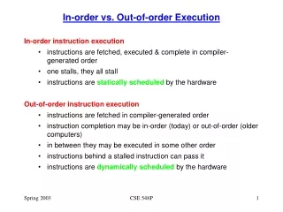
Dataflow Order Execution • Use data copying and/or hardware register renaming to eliminate WAR and WAW • register name refers to a temporary value produced by an earlier instruction (ISA perspective) • decouple register name from fixed storage location • disambiguate between register name reuse • Maintain a window (or windows) of several pending instructions with only RAW dependence • Issue instructions out-of-order • find instructions whose input operands are available • give preference to older instructions • A completing instruction’s result can trigger other pending instructions (RAW)
Diversified PipelinedInorder Issue, Out-of-order Complete • Multiple functional units (FU’s) • Floating-point add • Floating-point multiply/divide • Three register files (pseudo reg-reg machine in FP unit) • (4) floating-point registers (FLR) • (6) floating-point buffers (FLB) • (3) store data buffers (SDB) • Out of order instruction execution: • After decode the instruction unit passes all floating point instructions (in order) to the floating-point operation stack (FLOS). • In the floating point unit, instructions are then further decoded and issued from the FLOS to the two FU’s • Variable operation latencies (not pipelined): • Floating-point add: 2 cycles • Floating-point multiply: 3 cycles • Floating-point divide: 12 cycles
Reservation Station • Buffers where instructions can wait for RAW hazard resolution and execution • Associate more than one set of buffering registers (control, source, sink) with each FU virtual FU’s. • Add unit: three reservation stations • Multiply/divide unit: two reservation stations • Pending (not yet executing) instructions can have either value operands or pseudo operands (aka. tags). RS1 RS2 RS1 RS2 Mult Mult Mult
Rename Tags • Register names are normally bound to FLR registers • When an FLR register is stale, the register “name” is bound to the pending-update instruction • Tags are names to refer to these pending-update instructions • In Tomasulo, A “tag” is statically bound to the buffer where a pending-update instruction waits. • 6 FLB’s • 5 reservation stations (3 add RSs, 2 multiply/divide RSs) 4-bit tag is needed to identify the 11 potential sources • Instructions can be dispatched to RSs with either value operands or just tags. • Tag operand unfulfilled RAW dependence • the instruction in the RS corresponding to the Tag will produce the actual value eventually
Common Data Bus (CDB) • CDB is driven by all units that can update FLR • When an instruction finishes, it broadcasts both its “tag” and its result on the CDB. • Why don’t we need the destination register name? • Sources of CDB: • Floating-point buffers (FLB) • Two FU’s (add unit and the multiply/divide unit) • The CDB is monitored by all units that was left holding a tag instead of a value operand • Listens for tag broadcast on the CDB • If a tag matches, grab the value • Destinations of CDB: • Reservation stations • Store data buffers (SDB) • Floating-point registers (FLR)
Superscalar Execution Check List INSTRUCTION PROCESSING CONSTRAINTS Resource Contention Code Dependences (Structural Dependences) Data Dependences Control Dependences (RAW) True Dependences Storage Conflicts Anti-Dependences (WAR) Output Dependences (WAW)
Structural Dependence Resolution • Structural dependence: virtual FU’s • FLOS can hold and decode up to 8 instructions. • Instructions are dispatched to the 5 reservation stations (virtual FU’s) even though there are only two physical FU’s. • Hence, structural dependence does not stall decoding Why is this useful?
Resolving True-Dependence • True dependence: Tags + CDB • If an operand is available in FLR, it is copied to RS • If an operand is not available then a tag is copied to the RS instead. This tag identifies the source (RS/instruction) of the pending write • Eventually the source instruction completes and broadcasts its tag and value on the CDB • Any reservation station entry, FLR entry or SDB entry that holds a matching tag as operand will latch in the broadcasted value from the CDB. RAW dependence does not block subsequent independent instructions and does not block an FU
RAW Example: i: R2 R0 + R4 j: R8 R0 + R2 Cyc #1: Cyc #2: Cyc #3:
RAW Example: i: R2 R0 + R4 j: R8 R0 + R2 Cyc #1: dispatch i Cyc #2: dispatch j Cyc #3: i in RS1 broadcasts tag and result: CBD=<<1,16.0>>
Resolving Anti-Dependence • Anti-dependence: Operand Copying • If an operand is available in FLR, it is copied to RS with the issuing instruction • By copying this operand to RS, all WAR dependencies due to future writes to this same register are resolved Hence, the reading of an operand is not delayed, possibly due to other dependencies, and subsequent writes are also not delayed.
i: R4 R0 x R8 j: R0 R4 x R2 k: R2 R2 + R8 WAR Example: Cyc #1: Cyc #2: Cyc #3:
i: R4 R0 x R8 j: R0 R4 x R2 k: R2 R2 + R8 WAR Example: Cyc #1: dispatch i Cyc #2: dispatch j & k (assume dual issue) Cyc #3:
i: R4 R0 x R8 j: R0 R4 x R2 k: R2 R2 + R8 WAR Example: Cyc #4: RS 1 and 4 completes CBD=<<1,11.3>> & <<4,46,8>>
Resolving Output-Dependence • Output dependence: “register renaming” + result forwarding • If a FLR is waiting for a pending write, it’s tag field will contain the tag of the source instruction • If a 2nd instruction comes along and want to write the same register • the register can be renamed to the 2nd instruction (i.e. new tag) • Any instruction that needs the value of the 1st pending write has the tag of the 1st instruction. Hence, the correct value will be forwarded from the 1st instruction directly • any subsequent instruction that reads the register will get the tag, or eventually the result, of the 2nd instruction WAW dependence is resolved without stalling a physical functional unit and does not require additional buffers to ensure sequential write back to the register file.
i: R4 R0 x R8 j: R2 R0 + R4 k: R4 R0 + R8 l: R8 R4 x R8 WAW Example: Cyc #1: Cyc #2: Cyc #3:
i: R4 R0 x R8 j: R2 R0 + R4 k: R4 R0 + R8 l: R8 R4 x R8 WAW Example: Cyc #4: Cyc #5: Cyc #6:
i: R4 R0 x R8 j: R2 R0 + R4 k: R4 R0 + R8 l: R8 R4 x R8 WAW Example: Cyc #1: dispatch i and j Cyc #2: dispatch k and l Cyc #3:
i: R4 R0 x R8 j: R2 R0 + R4 k: R4 R0 + R8 l: R8 R4 x R8 WAW Example: Cyc #4: RS 2 and 4 completes: CBD=<<2,13k8>> & <<4,46,8>> Cyc #5: Cyc #6:
w w: R4 R0 + R8 x: R2 R0 x R4 y: R4 R4 + R8 z: R8 R4 x R2 x y z Code Sequence for Example 4