SPiiPlus Training Class
SPiiPlus Training Class. MC4U Trainer Setup. Presentation Contents. Introduction EtherCAT Configurator walkthrough System Configuration Wizard walkthrough System Information Viewer Complete setup of a single axis on an ACS drive. Introduction.

SPiiPlus Training Class
E N D
Presentation Transcript
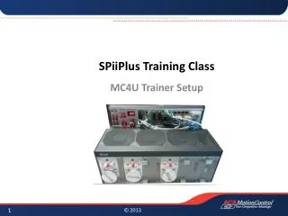
SPiiPlus Training Class MC4U Trainer Setup
Presentation Contents • Introduction • EtherCAT Configurator walkthrough • System Configuration Wizard walkthrough • System Information Viewer • Complete setup of a single axis on an ACS drive
Introduction • This presentation is a step-by-step setup of the MC4Unt trainer unit. It is meant to give a flavor of what a real system setup is like. • Setup in the presentation was done using SPiiPlus MMI Application Studio 2.10 software. The latest version can be found at acsmotioncontrol.com • There are three main setup tasks for the trainer unit: • EtherCAT network configuration • System configuration • Axis setup and tuning • The trainer unit has three axes. This presentation covers setup of one axis, the other two are up to you!
MC4U Trainer Contents 4 1 3
Establish Communication with Controller • Connect an Ethernet cable between the PC and the MC4U (J6-ETH1) • Open the MMI, and User Mode Driver (if not already running) • Set ‘Controller IP Address’ to 10.0.0.100 and make sure your PC is on the same network, then click ‘Connect’ • When connection is established, the workspace window shows a green LED next to the connected controller’s serial number
Add Components to Workspace • Right-click on the controller in the workspace window and select ‘Add Component’ to add the following: • Setup Adjuster Wizard • Setup System Configuration Wizard • Setup EtherCAT Configurator • Utilities System Information Viewer • Utilities Communication Terminal • Application Development Program Manager
EtherCAT Configurator • Double click ‘EtherCAT Configurator’ componentin the workspace tree to open • Select ‘Scan System’ and the connectedEtherCAT network will be displayed • Click ‘Generate Configuration’to save to flash • Wait for controller to reboot • Close EtherCAT Configurator
System Configuration • Double click ‘System Configuration Wizard’in the workspace tree to open • Select ‘Change System Configuration’radio button, click next • Leave application details blank, click next • Click ‘Approve All’ at bottom ofscreen, click next • When prompted to save configuration to controller’s flash, select yes, and OK to reboot • Click next to skip COC and Print Reports. Click ‘Finish’ to close System Configuration Wizard
System Information Viewer • Double click ‘System Information Viewer’in the workspace tree to open • Any relevant information about a system can be found using the System Information Viewer, as well as save/load system information
System Information Viewer • For instance, to view which IO are available: look under System Configuration Network Units Unit 0 Inputs/Outputs Assignment • Looking at the pane to the right, there are 8 digital I/O, and 4 analog I/O
Adjuster Wizard • Double click ‘Adjuster Wizard’ in theworkspace tree to open • Specify you are working with Axis 3 • Select ‘Setup New System or Controller’option • Click next to get to ‘Initialization’ • Leave user information blank, click next to get to ‘Axis Structure’
Adjuster Wizard: Axis Structure • Specify axis structure as ‘Single Motor’ • Specify motor-load topology as ‘Rotary Motor and Rotary Load – Direct Drive’ • Set feedback topology as ‘Single, on motor’ • Apply user units to motor • Select ‘Degrees’ as rotary units • Press ‘Next’ button
Adjuster Wizard: Motor • Press the ‘+’ button to add a new motor • Enter the following motor data: • Click next
Adjuster Wizard: Drive • Press the ‘+’ button to add a drive • The ACS drive will automatically be recognized except supply input voltage and/or frequency • Specify the input voltage as 110V • Specify frequency as 60Hz • Click next
Adjuster Wizard: Motor Feedback • Press the ‘+’ button to add a new motor feedback • Select the motor feedback type as ‘Incremental Quadrature Encoder’ • Specify the resolution as 2048 lines per revolution • Set the external multiplier to 1 • Click next
Adjuster Wizard: Calculate Parameters • Click ‘Calculate Parameters’ • A list of all calculatedparameters differentfrom current values isshown • Click ‘Apply Changes’to update all parametersto the newly calculatedvalues • Click next
Adjuster Wizard: Safety and Protection • Skip to ‘Current Limits’ by clicking onit in the task pane • The adjuster sets current limits toprevent damage to the motor based oninfo entered in ‘Components’. It is importantto verify it is correct • Click next to get to ‘Position Errors’ • Position error parameters are set automatically too, but these may need to be relaxed temporarily for tuning purposes !!! Important Safety Info !!!
Adjuster Wizard: Verification • Skip to ‘Switches’ under the ‘Verification’heading by clicking on it in the task pane • Verify upper and lower limit switchfunctionality and inverse logic if necessary • Click nextto get to ‘Stop, Alarm and Brake’ • Verify Hardware Emergency Stop functionalityand inverse logic if necessary • Click next !!! Important Safety Info !!!
Adjuster Wizard: Axis Setup and Tuning • The Axis Setup and Tuning process iscovered in detail in the ‘SPiiPlus TimeDomain Tuning’ presentation, but in generalinvolves: • Current loop tuning • Motor commutation • Velocity loop tuning • Position loop tuning
Adjuster Wizard: Axis Setup and Tuning • ACS utilizes a cascaded control loop structure, ideal for motion control applications: • Current loop • Velocity loop • Position loop • The position loop generates a command to the velocity loop • The velocity loop generates a command to the current loop
Adjuster Wizard: Axis Setup and Tuning • Tuning rules of thumb: • For current and velocity loops: • Begin by setting proportional and integrator gains low (usually 10 is fine for both) • Start by doubling proportional gain until response is noisy, then reduce by half • Keep proportional gain fixed and begin doubling integrator gain until roughly 10-15% overshoot is observed • For position loop: • Start low (usually 10) and begin doubling until position error is minimized. • Make sure position error while moving at constant velocity is not noisy.
Adjuster Wizard: Current Loop Tuning • Set both SLIKP and SLIKI = 10 (start out low) • Default current level is 10% with 4ms pulse width. These values are fine, do not change. • Click ‘Scope Autoset’ and ‘Run’ • Double SLIKP until high frequency effects (noise) or overshoot are present, then reduce by half. • Typical values: 50 – 500 • Changing SLIKI should not require returning the change SLIKP • Double SLIKI until overshoot is excessive, then reduce by half. Overshoot should be roughly 10-15% • Typical values: 1000 – 10,000
Adjuster Wizard: Commutation • Commutation is the process of keeping current vector perpendicular to motor magnetic field vector. • Handled automatically in brush DC motors, and not necessary in steppers operating in micro-stepping mode. • At controller startup the magnetic field orientation of a BLDC motor is not known and needs to be found. The adjuster has a facility for finding it and setting the commutation angle. • Once found, the commutation angle is kept track of using motor feedback (encoder)
Adjuster Wizard: Commutation • Adjuster based commutation only needs to be done once during initial axis setup. • Once axis is properly setup and tuned, ACSPL+ COMMUT command can be used instead. • COMMUT command pings motor three times and finds commutation angle with very little physical motion. • If motor is equipped with hall sensors, commutation angle is based on first hall state transition, and COMMUT command is not necessary.
Adjuster Wizard: Commutation • In the commutation dialog, click the ‘default’ button to tailor the commutation process for this particular axis • Click ‘Start Commutation’ • On top of finding the commutation angle, a number of magnetic pitches will be measured and checked against encoder feedback to verify settings • On successful commutation, click next twice to skip to ‘Position and Velocity Loops’
Adjuster Wizard: Position and Velocity Loops • Select ‘Velocity Loop’ • Click ‘Motion Manager Autoset’, and ‘ScopeAutoset’ • The only variables you need to be concerned with in velocity loop tuning are Proportional Gain (SLVKP), and Integrator Gain (SLVKI) • Start SLVKP, SLVKI lowand use a similar tuningapproach as in current loop • In Motion Manager, click ‘EnableMotor’ and ‘Start Motion’
Adjuster Wizard: Position and Velocity Loops • Select ‘Position Loop’ • Click ‘Motion Manager Autoset’ and ‘ScopeAutoset’ • Enter the following settings in the MotionManager: • Click ‘Enable Motor’ then ‘Start Motion’
Adjuster Wizard: Position and Velocity Loops • The only variable you need to be concerned with in position loop tuning is Proportional Gain (SLPKP) • Start SLPKP low and doubleuntil position error is minimizedwhile making sure it is notnoisy at constant velocity.
Adjuster Wizard: Save to Flash Once all previous steps are complete the system is now setup and tuned. Save to flash so it will be available on controller startup.