Download

1 / 104
1.06k likes | 1.11k Views
Delve into the world of networking hardware building blocks like nodes and links, covering physical media types and terminology. Gain insights on last-mile, Central Subscriber office links, wireless technologies, encoding, framing, and error detection in point-to-point links. Learn about key concepts such as Shannon’s Theorem and explore various encoding approaches like NRZ, Manchester, 4B/5B, and framing techniques. Unravel the mysteries of how data is transmitted between network nodes and how signals are encoded and decoded.

E N D
Hardware building blocks • Nodes • like desktop workstations, PC’s, switches, routers, and so on • Links • physical media such as twisted pair wire, coax cable, optical fiber, space, and so on.
Nodes • Connects to network via a network adaptor • Fast processor, slow and finite memory
Links • Physical Media • Conducted media • twisted pair wire • coax cable • optical fiber • Radiated media • radio waves • microwaves • infrared beams
Typical Link Bandwidths Sometimes you install your own Sometimes leased from the phone company
Terminology • DS1 stands for data signaling 1, also called T-1 • STS-1: STS stands for synchronous transport signal • POTS: Plain old telephone system • ISDN: Integrated digital service network • DSL: Digital subscriber line • CATV: Cable TV
Last-Mile Links • Connecting home PC’s or networks to Internet
1.554 ─ 8.448 Mbps 16 ─ 640 Kbps Central Subscriber office premises Local loop ADSL Service • Service is provided over the existing telephone line (18,000-9,000 feet)
─ 55.2 Mbps VDSL at 12.96 STS- N Neighbourhood optical Central Subscriber network unit office over fiber ─ 4500 feet of copper premises over 1000 VDSL Service • Supports very high data rate
Wireless Links • Well tested technology • Use radio waves and microwaves • Rapidly growing • Supported with satellite constellations to cover the entire earth • AMPS based on analog technology is giving way to digital cellular PCS and GSM AMPS – Advanced Mobile Phone System PCS – Personal Communication Services GSM – Global System for Mobile Communication
Shannon’s Theorem • Can be used to determine the data rate at which a modem can be expected to transmit binary data. • It is given by the formula C = Blog2(1 + S/N) where C is the achievable channel capacity, B is the bandwidth of the line, S is the average signal power and N is the average noise power. The signal-to-noise ratio is usually expressed in decibels, related as follows: db = 10 ×log10(S/N)
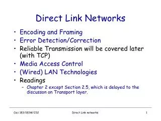
Outline Encoding Framing Error Detection Sliding Window Algorithm Point-to-Point Links
Questions • How bits can be transmitted from one node to the other? • Who transmits bits and in which form? • Note: The network adaptor contains a signaling component that actually encodes bits into signals at the sending node and decodes signals into bits at the receiving node.
Encoding • Signals propagate over a physical medium • modulate electromagnetic waves • e.g., vary voltage • Signals travel over a link between two signalling components, and bits flow between network adaptors
Encoding (contd..) • Encode binary data onto signals • e.g., 0 as low signal and 1 as high signal • known as Non-Return to zero (NRZ)
Problem: Consecutive 1s or 0s • The problem of consecutive 1s or 0s leads to a situation called baseline wander • Receiver keeps an average of the signal • When signal is lower than average it is treated as a 0, otherwise treated as a 1 • Unable to recover the clock (Clock recovery problem)
Alternative Encodings • Non-return to Zero Inverted (NRZI) • make a transition from current signal to encode a one; stay at current signal to encode a zero • solves the problem of consecutive ones • Manchester • transmit XOR of the NRZ encoded data and the clock • only 50% efficient. (bit rate is half the baud rate) • 0 is encoded as a low-to-high transition and 1 encoded as a high-to-low transition
Alternative Encodings (contd..) • 4B/5B (Refer to Table 2.4 4B/5B encoding) • every 4 bits of data encoded in a 5-bit code • 5-bit codes selected to have no more than one leading 0 and no more than two trailing 0s • thus, never get more than three consecutive 0s • resulting 5-bit codes are transmitted using NRZI • achieves 80% efficiency
Framing • A frame is a sequence of bits • Exchanged between adaptors • Break sequence of bits into a frame • Typically implemented by network adaptor
Question • How does the receiving network adaptor know where a frame begins and ends?
Approaches • Sentinel-based, bit-oriented • delineate frame with special pattern: 01111110 • e.g., HDLC, SDLC, PPP • problem: special pattern appears in the payload • solution: bit stuffing • sender: insert 0 after five consecutive 1s • receiver: delete 0 that follows five consecutive 1s
Approaches (contd..) • Sentinel approach, byte oriented • BISYNC • Problem: ETX character might appear in the data portion of the frame • Solution: Escape the ETX character with a DLE character in BISYNC; escape the DLE character with a DLE character. • Control characters • DLE - Data Link Escape character • SOH - Start of Header character • SYN - Synchronization character • ETX - End of Text character • STX - Start of Text character
Terminology • HDLC - High-Level Data Link Control protocol • SDLC - Synchronous Data Link Control protocol • DDCMP - Digital Data Communication Message Protocol • BISYNC - Binary Synchronous Communication • PPP - Point-to-Point Protocol
Approaches (contd..) • Counter-based • include payload length in header • e.g., DDCMP • problem: count field corrupted • solution: catch when CRC fails • CRC stands for Cyclic Redundancy Check
HDLC • HDLC denotes both the beginning and end of a frame with the distinguished bit sequence 01111110 • The sender inserts a 0 before the transmitting the next bit if it sees five consecutive 1s in the body of the message • On the receiver side, should five consecutive 1s arrive, the receiver makes its decision based on the next bit it sees. If the next bit is a 0, it must have been stuffed, and the receiver removes it. If the next bit is a 1, then two things are possible, if it sees a 0, then it is the end of frame marker, if it sees a 1, then there must have been an error and the whole frame is discarded
Approaches (contd..) • Clock-based • each frame is 125ms long • e.g., SONET: Synchronous Optical Network • STS-n (STS-1 = 51.84 Mbps)
Approaches (contd..) • Each STS-1 frame has nine rows • Each row contains 90 bytes, the first 3 bytes of each are overhead • The first two bytes of the frame contain a special bit pattern that enables the receiver to determine where the frame begins • Receiver looks for the special bit pattern at every 810 bytes, since each frame is 9 × 90 = 810 bytes long. • STS-48: 48 × 51.84 = 2488.32 Mbps
Error Detection • Bits can change on their way to destination mainly due to noise • Known as errors • How can you detect whether a packet is in error or not? • Sender calculates some code or checksum on the content of a packet and includes it in the packet • Receiver makes use of the code or checksum to verify the integrity of the packet
Two-Dimensional Parity • Add one extra bit to a 7-bit code to balance the number of 1s in the byte to either odd or even count. • Add a bit position across each of the bytes contained the frame, which results in an extra parity byte.
Internet Checksum Algorithm • Not used at the link level • Used at the transport level for an end-to-end protocol • Basic idea • Consider data as a sequence of 16-bit integers • Add them together using 16-bit ones complement arithmetic • Finally take the ones complement of the result to obtain the checksum • Transmit data and checksum together • Receiver performs the same calculation on the received data and compares the result with the received checksum
Internet Checksum Algorithm • View message as a sequence of 16-bit integers; sum using 16-bit ones-complement arithmetic; take ones-complement of the result. u_short cksum(u_short *buf, int count) { register u_long sum = 0; while (count--) { sum += *buf++; if (sum & 0xFFFF0000) { /* carry occurred, so wrap around */ sum &= 0xFFFF; sum++; } } return ~(sum & 0xFFFF); }
Comments on Internet Checksum • Works well for a few redundant bits in a packet (only 16 bits) • Not as good as CRC for error detection • Simple • Can be implemented easily in software • Provides the last line of defense in an end-to-end protocol
Cyclic Redundancy Check (CRC) • Add k bits of redundant data to an n-bit message • want k << n • e.g., k = 32 and n = 12,000 (1500 bytes) • Represent n-bit message as n-1 degree polynomial • e.g., MSG=10011010 as M(x) = x7 + x4 + x3 + x1 • Let k be the degree of some divisor polynomial • e.g., C(x) = x3 + x2 + 1 • bit pattern is 1101
CRC (contd..) • Transmit polynomial P(x) (MSG and k bits) that is evenly divisible by C(x) • shift left k bits, i.e., M(x)xk = T(x) • subtract remainder of T(x) / C(x) from T(x) • Note: arithmetic is done on modulo 2 basis • Receiver polynomial P(x) + E(x) E(x) = 0 implies no errors • Divide (P(x) + E(x)) by C(x); remainder zero if: • E(x) was zero (no error), or • E(x) is exactly divisible by C(x)
CRC (contd..) • Sender • Multiply M(x) by xk; for our example, we get x10+ x7 + x6+ x4 (10011010000) • Divide result by C(x) (1101); Remainder is 101 • Send 10011010000 - 101 = 10011010101, since this must be exactly divisible by C(x)
CRC (contd..) • Receiver • Receives the bit-stream 10011010101 (in case of no error) • Divides 10011010101 by 1101 • Checks whether the remainder is 000 • Declares the frame is in error if remainder is not 000
Selecting C(x) • All single-bit errors, as long as the xk and x0 terms have non-zero coefficients. • All double-bit errors, as long as C(x) contains a factor with at least three terms • Any odd number of errors, as long as C(x) contains the factor (x + 1) • Any ‘burst’ error (i.e., sequence of consecutive error bits) for which the length of the burst is less than k bits. • Most burst errors of larger than k bits can also be detected
Common polynomials for C(x) CRC CRC-8 CRC-10 CRC-12 CRC-16 CRC-CCITT CRC-32 C(x) x8+x2+x1+1 x10+x9+x5+x4+x1+1 x12+x11+x3+x2+x1+1 x16+x15+x2+1 x16+x12+x5+1 x32+x26+x23+x22+x16+x12+x11+x10+x8+x7+x5+x4+x2+x+1
Comments on CRC • Ethernet and 802.5 networks use CRC-32 • HDLC uses CRC-CCITT • ATM uses CRC-8, CRC-10, and CRC-32 • Easily implemented in hardware using a shift register and XOR gates
Problem • How can we achieve reliability in data communications over unreliable links that can introduce random errors? • Answer: • Use some combination of two mechanisms: acknowledgements (ACK) and timeouts • Known as automatic repeat request (ARQ)
Acknowledgements & Timeouts Cases: a) ACK is received before timeout b) Frame is lost c) ACK is lost d) Timeout fires too soon
Stop-and-Wait • The simplest ARQ scheme • Sender • Transmit a frame • Wait for ACK before transmitting the next frame • If ACK arrives on time, send the next frame; otherwise send the original frame • Receiver • Check the frame received • If no error, send ACK; otherwise discard the frame
Stop-and-Wait (contd..) • Problem: • Retransmission of frames can cause duplication at the receiver. • Solution – Frame Sequence numbers • Sender: Include a sequence number for each frame transmitted • Receiver: Check the sequence number field for possible duplication • 1-bit sequence number field is needed for Stop-and-Wait protocol.
Stop-and-Wait (contd..) • Problem: keeping the pipe full • Example • 1.5Mbps link x 45ms RTT = 67.5Kb (8KB) • Implies a max sending rate of: (1KB /45ms) • 1KB frames implies 1/8th link utilization Sender Receiver