Download
1 / 17
190 likes | 350 Views
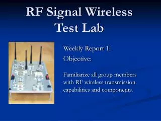
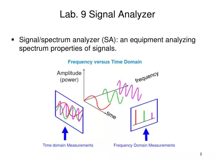
Lab. 9 Signal Analyzer S ignal/spectrum analyzer (SA): an equipment analyzing spectrum properties of signals. 1. T ype of SA: S wept (downconvert one carrier at a time) F ourier (downconvert a band of carrier at a time). 2. S wept analyzer:. 3. R esolution bandwidth:

E N D
Lab. 9 Signal Analyzer Signal/spectrum analyzer (SA): an equipment analyzing spectrum properties of signals. 1
Type of SA: • Swept (downconvert one carrier at a time) • Fourier (downconvert a band of carrier at a time) 2
Resolution bandwidth: • The higher the resoultion, the slower the scan. 4
Vector signal analyzer: • A SA that can conduct demodulation 5
Agilent approach: Software Hardware 7
Software analyzer: • Analyze the signal recorded by hardware • Load recorded signal: • File Recall Recall demo (Help Signals) QPSK • Four windows (traces) are usually used: • Time constellation • Spectrum • EVM (time) • EVM (average number) • Find the length of the recoded signal: • Window Player • Find the properties of the recorded signal: • Help Demo 8
Use the label of each window to select what you want to see • Time • IQ measurement • Spectrum • Use the unit of y-axis to have more selections • Adjust the overlayed percentage: • MeasSetup Frequency Time • Change MaxOverlapp • The higher the percentage, the slow the time sweep. • Find out the demodulation properties: • MeasSetup Digital demodulation properties 11
Use markers: • Add markers from the command bar • Marker Calculation select band power (set the center frequency and bandwidth) • Can also use mouse to draw the band. • Use OBW to select the band automatically. • The connect used for general equipment is BNC and that for RF transmission is SMA. For SA, we need to plug SMA into N type. We need some kind of connector transferring SMA to BNC. • The transmitter and receiver are not ideal in real-world. We have to give specifications for their performance so as to insure reliable communications. 12
Analog/RF Impairments: • DAC • Transmit IQ imbalance • Phase noise of the mixer • PA nonlinearity • Channel effect • Noise • Receive IQ imbalance • DC offset • Phase noise of the mixer • ADC • Carrier frequency offset • Digital processing: • Precision (fixed-point processing) • Receiver algorithms
How to test/specify a communication system? • Transmitter/receiver performance (separated) • Combine all impairments (combined) • Transmitter: • Transmit signal distortion (for receiver) • Spectrum characteristic (for interference control) • Indices for transmitter • Error vector magnitude (EVM) • Spectrum mask • Index for receiver: • Sensitivity • Interference performance * EVM is usually used for QAM signals.
EVM: • A signal sent by an ideal transmitter would have all constellation point at the ideal locations • For real-world transmitter, however, the constellation points will deviate from the ideal locations in a random fashion. • EVM is a measure of how far the constellation points are from the ideal locations * - 40dB~1.00% * - 30dB~3.16%
Spectrum mask: • Confine the spectrum used for transmission (interference control for the Bluetooth system) 20dB 20dB
Practice 1: • Choose at least two kind of signals and analyze the performance of the transmitters.