Download
1 / 30
300 likes | 475 Views
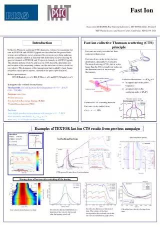
High-resolution Thomson Scattering (TVTS) Diagnostics On HT-7 tokamak Chunqiang Shao, Xiaofeng Han, Xiaoqi Xi, Junyu Zhao 2011-07-20. Outline. 1 Thomson scattering. 2 TVTS system on HT-7 tokamak.

E N D
High-resolution Thomson Scattering (TVTS) Diagnostics On HT-7 tokamak Chunqiang Shao, Xiaofeng Han, Xiaoqi Xi, Junyu Zhao 2011-07-20
Outline 1 Thomson scattering 2 TVTS system on HT-7 tokamak 3 Improvements for this spring experiment 4 System Performance
Principle laser injected into the plasma will be scattered by the electrons. While the velocity distribution of electrons is Maxwellian, the scattering power spectrum will be Gaussian. Due to the thermal motion of the electrons, the scattering spectrum is Doppler broadened: its width is proportional to the square root of the local Te. The number of scattered photons is proportional to the number of electrons in the scattering volume(means thene in a fixed volume). Thomson scattering
Hot plasma In the relativistic, isotropic plasma, the spectrum will shift to the blue side.and the shape factor of scattering power spectrum should be relativistic corrected: Thomson scattering • the relation between the • spectrum's width and Te For 1KeV electrons, there will be 10nm Drift.
Outline 1 Thomson scattering 2 TVTS system on HT-7 tokamak 3 Improvements for this spring experiment 4 System Performance
TVTS system on HT-7 tokamak collection lens fibers High throughput transmission grating spectrometer • image intensifier lens • coupled with an EMCCD • a short exposure time for • background light reduction • optimum SNR. HT-7 frequency multiplier ~2.2J Nd:YAG laser, 1064nm,4.2J ~1.8J is mostly 532nm ~2.0J efficiency of SHG>66% reflector(99% at 523nm,very low at 1064nm) focusing lens
Superguide SPCH (From Fiberguide CO.) Fiber 90 + 10 fibers, 15m SMA connectors 30 fibers for one spectrometer ,3m • Silica/hard clad, 0.8/0.83mm, NA of 0.39 • buffer stripped Alignment fibers with the monitor and motorized fiber holder to avoid the optical misalignment
High throughput transmission grating spectrometer Spectrometer and I-EMCCD An Improved CT spectrometer (transmission grating or refection grating)
The transmission of the trans.grating spectrometer we used Spectrometer and I-EMCCD
Image Intensifier lens coupled with an EMCCD A short exposure time for background reduction and match up to the pulse's width—— Image Intensifier (the switch of its power is controlled by a DG535) Optimum SNR ——EMCCD (volt) Spectrometer and I-EMCCD I.I. : suply voltage-Gain Curve
An Optimal Parameter I.I suply voltage (4.85V, 8000times enlarge but the efficiency of the screen is 0.01) The Program binning(1*100, 3 Fibers, Corresponded to10mm) EM Gain(24) Spectrometer and I-EMCCD The Quantum efficiency curve of Andor Ixon DV885 EMCCD
Outline 1 Thomson scattering 2 TVTS system on HT-7 tokamak 3 Improvements for this spring experiment 4 System Performance
This round: Used the own reflectors (90% at 532 nm) and collection lens for TV system. Improve the efficiency of frequency multiplier to >66% with adjusting frequency-doubling crystal(The reflectors on EAST were coated for both 1064nm and 532nm, and the pulse we measured its energy contained both 1064nm and 532nm lights, so we didn't realize the content of the 532nm light was very low last round) Improvements
The Timing Sequence of system (design a most optimal one for probing the background) Timing Sequence Acquisition time TS signal Lens and fibers Spectrometer Image Intensifier EMCCD Agilent DG535 Laser open gates Master Control get matched External trigger of laser The real TS signal time, width~15ns Acquisition time for signal and background, width~20ns The interval between the gates of signal and background was limited by the readout speed of EMCCD.
The laser is linearly polarized light, so does the Thomson scattering and stray light(use Notch Filter to remove it).But the plasma background and linear radiation are Non-polarized light. Wire-grid polarizer High Transmittance High Temperature Resistance Polaroid
The test of efficiency of polaroid (reduce the background and the linearly radiation) Polaroid Use the Polaroid linear radiation(Li)
Outline 1 Thomson scattering 2 TVTS system on HT-7 tokamak 3 Improvements for this spring experiment 4 System Performance
TS signal T-10 TVTS Use a filter to reduce the stray light compared with Parameter: 4.2J(1064nm), after frequency multiplier(532nm)~2.1J, then three reflector, ~1.8J, The gate 30ns(pluse width~20ns), Spatial resolution~9mm。
How to get the TS spectrum calibrate the Efficiency curve of system calibrate the Wavelength The signal-The background The TS signal The detection part of system broaden the signal ( Characterized by Instrument Function ) Deconvolution The real Spectrum of Thomson Scattering
T7 Tokamak TVTS Efficiency curve(Sensitivity curve) Relative calibration a.u. The Optical path for calibrating Efficiency curve (just the same path with the TV system) nm standard light source (Hg) lens the spectrometer We used a known spectrum(Hg) to substitute the TS spectrum. But we didn't know the energy we collect from the standard light source.
Wavelength Calibration 357.51nm 761.41nm the linear radiation of Lithium Slit width was seted to 200μm to obtain a high wavelength resolution,and the notch filter was not used. Then we use the linearly radiation of Lithium to calibrate the wavelength
Data Processing the TS signal(the signal cut background) the signal and background These are the shape factor of scatterig power spectrum with red points and the fitting curve with bule line. It should be noted that the efficiency curve has been calculated here.
Instrument Function g(x) s(x) f(x) Due to the convolution between the I.F. and the spectrum, the measured spectrum was been broadened the convolution formula: g(x)=s(x)*f(x) = ∫s(m)f(x-m)dm Enlarge Instrument Function(I.F.): use the stray light(532nm)with the same factors of sys to obtain the I.F. For the both two are Gaussian functions, their convolution is still a Gaussian function, and its width has the relation:
The range of measurement • IF broaden width : 10.2nm(1/e high width) • Filter bandwidth:17nm(Tavg<90%:37nm) • Wavelength range of Spectrometer:380nm-720nm Te: ~ 50eV to~ 5000eV
With different density The number of scattered photons is proportional to the localne. We can see the intensity of the spectrum became stronger very clearly with the density grow up.
With and without the LHW Green line:background time 10ms Binning: 3 Fibers. Typical point:15th~17th fibers. Up from the center corresponded to:24mm~30mm According to the temperature calculated we can see the effect of LHW heating. The TVTS sys. works! ~800eV ~1000eV
Temperature distribution Te/eV Z/mm
Summary • We have firtly proved the high resolution Thomson Scattering (TVTS) Diagnostic System to be capable of measuring the electrons' temperature this spring HT7 experiment. • We could give the Temperature distribution of the center of tokamak ( -10mm ~ 80mm ), and we chose 7 points have better data (0 mm ~ 60 mm, Spatial resolution~9mm). • The range of temperature we can measure : 50eV ~5000eV Acknowledgement The TV system was started building 3 years ago by Xiaoqi Xi with the help of our tutor Junyu Zhao. They made the great contributions.