Characterization and Simulation of the Cell Mechanical Environment using Finite Element Models
This project aims to quantify the 3D mechanical environment experienced by cells using advanced characterization techniques and finite element (FE) simulations. By accurately analyzing the geometry of fibrous matrices and integrating fiber properties, we inform FE models to determine local mechanical environments. The approach involves using confocal fluorescence microscopy, ABAQUS software, and energy partitioning to correlate the mechanical environment with cellular differentiation. These simulations are crucial for understanding how cells interact with their surroundings under cyclic excitation, shedding light on biomedical engineering applications.

Characterization and Simulation of the Cell Mechanical Environment using Finite Element Models
E N D
Presentation Transcript
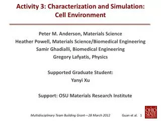
Activity 3: Characterization and Simulation:Cell Environment Peter M. Anderson, Materials Science Heather Powell, Materials Science/Biomedical Engineering Samir Ghadialli, Biomedical Engineering Gregory Lafyatis, Physics Supported Graduate Student: Yanyi Xu Support: OSU Materials Research Institute
Activity 3: Goal • Quantify • the 3D mechanical environment experienced by cells • Approach • accurately characterize fibrous matrix geometry • inform finite element models with • fiber properties • matrix geometry • matrix macromechanical response • use FE model to determine • local mechanical environment (Green's function) • cell force footprints • correlate environment and differentiation cyclic excitation
Activity 3: FE Simulations • Relates Structure and Properties mechanical properties: fibers matrix geometry Agarwal (AFMic) Powell/Ghadiali (OM)Lafyatis (DeCo) Ghadiali (SiWa) Finite Element Model mechanical response: matrix cell force footprint Powell (UniT) Anderson (NInd) energy partitioning
Activity 3: Matrix Geometry • Confocal Fluorescence Microscopy • heavy die loading/imaging (Powell/Ghadiali) • deconvolution (Lafyatis) • conversion to finite element data file (Ghadiali/Anderson)
Activity 3: Preliminary Simulations • ABAQUS software • 54 fibers: beam elements • 20 x 20 x 5 mm system • 110% axial strain • imposed in X direction. • Negative transverse strain • Possion effect Simu Scaffold Simulations LE fibers Ef = 1.11MPa Expe riments HyperE fibers LE FibersEf = 0.35MPa Z Y X