IEEE 802.11 Wireless LAN: DataLink Layer Overview
Dive into IEEE 802.11 wireless LAN technologies, including CSMA/CA protocols, multiple access strategies, and collision avoidance mechanisms.

IEEE 802.11 Wireless LAN: DataLink Layer Overview
E N D
Presentation Transcript
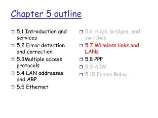
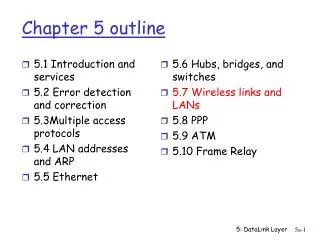
5.1 Introduction and services 5.2 Error detection and correction 5.3Multiple access protocols 5.4 LAN addresses and ARP 5.5 Ethernet 5.6 Hubs, bridges, and switches 5.7 Wireless links and LANs 5.8 PPP 5.9 ATM 5.10 Frame Relay Chapter 5 outline 5: DataLink Layer
802.11b 2.4-5 GHz unlicensed radio spectrum up to 11 Mbps direct sequence spread spectrum (DSSS) in physical layer all hosts use same chipping code widely deployed, using base stations 802.11a 5-6 GHz range up to 54 Mbps 802.11g 2.4-5 GHz range up to 54 Mbps All use CSMA/CA for multiple access All have base-station and ad-hoc network versions IEEE 802.11 Wireless LAN 5: DataLink Layer
Base station approch • Wireless host communicates with a base station • base station = access point (AP) • Basic Service Set (BSS) (a.k.a. “cell”) contains: • wireless hosts • access point (AP): base station • BSS’s combined to form distribution system (DS) 5: DataLink Layer
Ad Hoc Network approach • No AP (i.e., base station) • wireless hosts communicate with each other • to get packet from wireless host A to B may need to route through wireless hosts X,Y,Z • Applications: • “laptop” meeting in conference room, car • interconnection of “personal” devices • battlefield • IETF MANET (Mobile Ad hoc Networks) working group 5: DataLink Layer
IEEE 802.11: multiple access • Collision if 2 or more nodes transmit at same time • CSMA makes sense: • get all the bandwidth if you’re the only one transmitting • shouldn’t cause a collision if you sense another transmission • Collision detection doesn’t work: hidden terminal problem 5: DataLink Layer
IEEE 802.11 MAC Protocol: CSMA/CA 802.11 CSMA: sender - if sense channel idle for DISF sec. then transmit entire frame (no collision detection) -ifsense channel busy then binary backoff 802.11 CSMA receiver - if received OK return ACK after SIFS (ACK is needed due to hidden terminal problem) 5: DataLink Layer
Collision avoidance mechanisms • Problem: • two nodes, hidden from each other, transmit complete frames to base station • wasted bandwidth for long duration ! • Solution: • small reservation packets • nodes track reservation interval with internal “network allocation vector” (NAV) 5: DataLink Layer
Collision Avoidance: RTS-CTS exchange • sender transmits short RTS (request to send) packet: indicates duration of transmission • receiver replies with short CTS (clear to send) packet • notifying (possibly hidden) nodes • hidden nodes will not transmit for specified duration: NAV 5: DataLink Layer
Collision Avoidance: RTS-CTS exchange • RTS and CTS short: • collisions less likely, of shorter duration • end result similar to collision detection • IEEE 802.11 allows: • CSMA • CSMA/CA: reservations • polling from AP 5: DataLink Layer
5.1 Introduction and services 5.2 Error detection and correction 5.3Multiple access protocols 5.4 LAN addresses and ARP 5.5 Ethernet 5.6 Hubs, bridges, and switches 5.7 Wireless links and LANs 5.8 PPP 5.9 ATM 5.10 Frame Relay Chapter 5 outline 5: DataLink Layer
Point to Point Data Link Control • one sender, one receiver, one link: easier than broadcast link: • no Media Access Control • no need for explicit MAC addressing • e.g., dialup link, ISDN line • popular point-to-point DLC protocols: • PPP (point-to-point protocol) • HDLC: High level data link control (Data link used to be considered “high layer” in protocol stack! 5: DataLink Layer
PPP Design Requirements [RFC 1557] • packet framing: encapsulation of network-layer datagram in data link frame • carry network layer data of any network layer protocol (not just IP) at same time • ability to demultiplex upwards • bit transparency: must carry any bit pattern in the data field • error detection (no correction) • connection liveness: detect, signal link failure to network layer • network layer address negotiation: endpoint can learn/configure each other’s network address 5: DataLink Layer
PPP non-requirements • no error correction/recovery • no flow control • out of order delivery OK • no need to support multipoint links (e.g., polling) Error recovery, flow control, data re-ordering all relegated to higher layers! 5: DataLink Layer
PPP Data Frame • Flag: delimiter (framing) • Address: does nothing (only one option) • Control: does nothing; in the future possible multiple control fields • Protocol: upper layer protocol to which frame delivered (eg, PPP-LCP, IP, IPCP, etc) 5: DataLink Layer
PPP Data Frame • info: upper layer data being carried • check: cyclic redundancy check for error detection 5: DataLink Layer
Byte Stuffing • “data transparency” requirement: data field must be allowed to include flag pattern <01111110> • Q: is received <01111110> data or flag? • Sender: adds (“stuffs”) extra < 01111110> byte after each < 01111110> data byte • Receiver: • two 01111110 bytes in a row: discard first byte, continue data reception • single 01111110: flag byte 5: DataLink Layer
Byte Stuffing flag byte pattern in data to send flag byte pattern plus stuffed byte in transmitted data 5: DataLink Layer
PPP Data Control Protocol Before exchanging network-layer data, data link peers must • configure PPP link (max. frame length, authentication) • learn/configure network layer information • for IP: carry IP Control Protocol (IPCP) msgs (protocol field: 8021) to configure/learn IP address 5: DataLink Layer
Final Exam Review Topics • Chapters 4 and 5 (plus some global knowledge of Chapter 3) 5: DataLink Layer
Chapter 4 roadmap 4.1 Introduction and Network Service Models 4.2 Routing Principles 4.3 Hierarchical Routing 4.4 The Internet (IP) Protocol 4.5 Routing in the Internet 4.6 What’s Inside a Router 5: DataLink Layer
Chapter 4 roadmap 4.1 Introduction and Network Service Models 4.2 Routing Principles • Link state routing • Distance vector routing 4.3 Hierarchical Routing 4.4 The Internet (IP) Protocol 4.5 Routing in the Internet 4.6 What’s Inside a Router 5: DataLink Layer
Graph abstraction for routing algorithms: graph nodes are routers graph edges are physical links link cost: delay, $ cost, or congestion level A D B E F C Routing protocol Routing 5 Goal: determine “good” path (sequence of routers) thru network from source to dest. 3 5 2 2 1 3 1 2 1 • “good” path: • typically means minimum cost path • other def’s possible 5: DataLink Layer
Dijkstra’s algorithm net topology, link costs known to all nodes accomplished via “link state broadcast” all nodes have same info computes least cost paths from one node (‘source”) to all other nodes gives routing table for that node iterative: after k iterations, know least cost path to k dest.’s Notation: c(i,j): link cost from node i to j. cost infinite if not direct neighbors D(v): current value of cost of path from source to dest. V p(v): predecessor node along path from source to v, that is next v N: set of nodes whose least cost path definitively known A Link-State Routing Algorithm 5: DataLink Layer
Iterative, asynchronous: each local iteration caused by: local link cost change message from neighbor: its least cost path change from neighbor Distributed: each node notifies neighbors only when its least cost path to any destination changes neighbors then notify their neighbors if necessary wait for (change in local link cost of msg from neighbor) recompute distance table if least cost path to any dest has changed, notify neighbors Distance Vector Routing: overview Each node: 5: DataLink Layer
aggregate routers into regions, “autonomous systems” (AS) routers in same AS run same routing protocol “intra-AS” routing protocol routers in different AS can run different intra-AS routing protocol special routers in AS run intra-AS routing protocol with all other routers in AS also responsible for routing to destinations outside AS run inter-AS routing protocol with other gateway routers gateway routers Hierarchical Routing 5: DataLink Layer
Chapter 4 roadmap 4.1 Introduction and Network Service Models 4.2 Routing Principles 4.3 Hierarchical Routing 4.4 The Internet (IP) Protocol • 4.4.1 IPv4 addressing • 4.4.2 Moving a datagram from source to destination • 4.4.3 Datagram format • 4.4.4 IP fragmentation • 4.4.5 ICMP: Internet Control Message Protocol • 4.4.6 DHCP: Dynamic Host Configuration Protocol • 4.4.7 NAT: Network Address Translation 4.5 Routing in the Internet 4.6 What’s Inside a Router 4.7 IPv6 4.8 Multicast Routing 4.9 Mobility 5: DataLink Layer
Internet AS Hierarchy Intra-AS border (exterior gateway) routers Inter-ASinterior (gateway) routers 5: DataLink Layer
Intra-AS Routing • Also known as Interior Gateway Protocols (IGP) • Most common Intra-AS routing protocols: • RIP: Routing Information Protocol • OSPF: Open Shortest Path First • IGRP: Interior Gateway Routing Protocol (Cisco proprietary) 5: DataLink Layer
Internet inter-AS routing: BGP • BGP (Border Gateway Protocol):the de facto standard • Path Vector protocol: • similar to Distance Vector protocol • each Border Gateway broadcast to neighbors (peers) entire path (i.e., sequence of AS’s) to destination • BGP routes to networks (ASs), not individual hosts • E.g., Gateway X may send its path to dest. Z: Path (X,Z) = X,Y1,Y2,Y3,…,Z 5: DataLink Layer
Router Architecture Overview Two key router functions: • run routing algorithms/protocol (RIP, OSPF, BGP) • switching datagrams from incoming to outgoing link 5: DataLink Layer
5.1 Introduction and services 5.2 Error detection and correction 5.3Multiple access protocols 5.4 LAN addresses and ARP 5.5 Ethernet 5.6 Hubs, bridges, and switches 5.7 Wireless links and LANs 5.8 PPP Chapter 5 outline 5: DataLink Layer
Link Layer Services • Framing, link access: • encapsulate datagram into frame, adding header, trailer • channel access if shared medium • ‘physical addresses’ used in frame headers to identify source, dest • different from IP address! • Reliable delivery between adjacent nodes • we learned how to do this already (chapter 3)! • seldom used on low bit error link (fiber, some twisted pair) • wireless links: high error rates • Q: why both link-level and end-end reliability? 5: DataLink Layer
Link Layer Services (more) • Flow Control: • pacing between adjacent sending and receiving nodes • Error Detection: • errors caused by signal attenuation, noise. • receiver detects presence of errors: • signals sender for retransmission or drops frame • Error Correction: • receiver identifies and corrects bit error(s) without resorting to retransmission • Half-duplex and full-duplex • with half duplex, nodes at both ends of link can transmit, but not at same time 5: DataLink Layer
Parity Checking Two Dimensional Bit Parity: Detect and correct single bit errors Single Bit Parity: Detect single bit errors 0 0 5: DataLink Layer
Checksumming: Cyclic Redundancy Check • view data bits, D, as a binary number • choose r+1 bit pattern (generator), G • goal: choose r CRC bits, R, such that • <D,R> exactly divisible by G (modulo 2) • receiver knows G, divides <D,R> by G. If non-zero remainder: error detected! • can detect all burst errors less than r+1 bits • widely used in practice (ATM, HDCL) 5: DataLink Layer
Multiple Access Links and Protocols Two types of “links”: • point-to-point • PPP for dial-up access • point-to-point link between Ethernet switch and host • broadcast (shared wire or medium) • traditional Ethernet • upstream HFC • 802.11 wireless LAN 5: DataLink Layer
MAC Protocols: a taxonomy Three broad classes: • Channel Partitioning • divide channel into smaller “pieces” (time slots, frequency, code) • allocate piece to node for exclusive use • Random Access • channel not divided, allow collisions • “recover” from collisions • “Taking turns” • tightly coordinate shared access to avoid collisions 5: DataLink Layer
Summary of MAC protocols • What do you do with a shared media? • Channel Partitioning, by time, frequency or code • Time Division,Code Division, Frequency Division • Random partitioning (dynamic), • ALOHA, S-ALOHA, CSMA, CSMA/CD • carrier sensing: easy in some technologies (wire), hard in others (wireless) • CSMA/CD used in Ethernet • Taking Turns • polling from a central site, token passing 5: DataLink Layer
LAN Addresses and ARP 32-bit IP address: • network-layer address • used to get datagram to destination IP network (recall IP network definition) LAN (or MAC or physical or Ethernet) address: • used to get datagram from one interface to another physically-connected interface (same network) • 48 bit MAC address (for most LANs) burned in the adapter ROM 5: DataLink Layer
LAN Addresses and ARP Each adapter on LAN has unique LAN address 5: DataLink Layer
Question: how to determine MAC address of B knowing B’s IP address? ARP: Address Resolution Protocol • Each IP node (Host, Router) on LAN has ARP table • ARP Table: IP/MAC address mappings for some LAN nodes < IP address; MAC address; TTL> • TTL (Time To Live): time after which address mapping will be forgotten (typically 20 min) 5: DataLink Layer
Routing to another LAN walkthrough: send datagram from A to B via R assume A know’s B IP address • Two ARP tables in router R, one for each IP network (LAN) • In routing table at source Host, find router 111.111.111.110 • In ARP table at source, find MAC address E6-E9-00-17-BB-4B, etc A R B 5: DataLink Layer
Ethernet Frame Structure Sending adapter encapsulates IP datagram (or other network layer protocol packet) in Ethernet frame Preamble: • 7 bytes with pattern 10101010 followed by one byte with pattern 10101011 • used to synchronize receiver, sender clock rates 5: DataLink Layer
Jam Signal: make sure all other transmitters are aware of collision; 48 bits; Bit time: .1 microsec for 10 Mbps Ethernet ;for K=1023, wait time is about 50 msec Exponential Backoff: Goal: adapt retransmission attempts to estimated current load heavy load: random wait will be longer first collision: choose K from {0,1}; delay is K x 512 bit transmission times after second collision: choose K from {0,1,2,3}… after ten collisions, choose K from {0,1,2,3,4,…,1023} Ethernet’s CSMA/CD (more) See/interact with Java applet on AWL Web site: highly recommended ! 5: DataLink Layer
Interconnecting LAN segments • Hubs • Bridges • Switches • Remark: switches are essentially multi-port bridges. • What we say about bridges also holds for switches! 5: DataLink Layer
Interconnecting with hubs • Backbone hub interconnects LAN segments • Extends max distance between nodes • But individual segment collision domains become one large collision domian • if a node in CS and a node EE transmit at same time: collision • Can’t interconnect 10BaseT & 100BaseT 5: DataLink Layer
Bridges • Link layer device • stores and forwards Ethernet frames • examines frame header and selectively forwards frame based on MAC dest address • when frame is to be forwarded on segment, uses CSMA/CD to access segment • transparent • hosts are unaware of presence of bridges • plug-and-play, self-learning • bridges do not need to be configured 5: DataLink Layer
Ethernet Switches • Essentially a multi-interface bridge • layer 2 (frame) forwarding, filtering using LAN addresses • Switching: A-to-A’ and B-to-B’ simultaneously, no collisions • large number of interfaces • often: individual hosts, star-connected into switch • Ethernet, but no collisions! 5: DataLink Layer