HF OPERATORS
HF OPERATORS. Notes on Lightning by John White VA7JW. LIGHTNING. THUNDER. Generation of Lightning. Thunderstorms Cold front - air aloft sinks Warm air at ground rises Vertical air flow, up and down Friction between water droplets Droplets become charged Charges separate within cloud

HF OPERATORS
E N D
Presentation Transcript
HF OPERATORS Notes on Lightning by John White VA7JW NSARC HF Operators
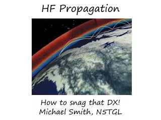
LIGHTNING THUNDER NSARC HF Operators
Generation of Lightning • Thunderstorms • Cold front - air aloft sinks • Warm air at ground rises • Vertical air flow, up and down • Friction between water droplets • Droplets become charged • Charges separate within cloud • High voltages develop • Within, cloud to cloud • Cloud to Earth • Air breakdown occurs • LIGHTING DISCHARGE NSARC HF Operators
Some Facts • Average duration 50 microseconds • Average speed of Lightning stroke 20,000 mph • Average Temperature 30,000 degrees C • Average Length 3 km • Average Energy 300,000,000 joules • Average Power 10,000,000,000,000 watts (10 terawatts) • Average number of strokes per flash, 4 • 200 thunderstorms in progress world wide any time • 100 flashes per second worldwide any time • Astraphobia – fear of thunder and lightning Reference “Lightning and Lightning Protection”, William Hard and Edgar Malone. Don White Consultants publisher 1979. and other internet sources. NSARC HF Operators
Forms of Lightning • Cloud to Ground – our major concern ! • Cloud discharge to ground • Within a cloud • Discharge in a cloud • Cloud to cloud • Discharge between clouds • Heat lightning • Intracloud, far away • Thunder not audible • Sheet Lightning • Intracloud, diffuse • Cloud to air • Bolt-from-the-blue Don White Consultants NSARC HF Operators
Annual Thunderstorm Days in America • Numbers are storm days • Florida is Worst - ( Adam AB4OJ/VA7OJ will vouch for that) Don White Consultants NSARC HF Operators
Annual Thunderstorm Days in Canada • We are lucky, only ~ 5 days per year IEEE ANSI/IEEE Std 142-1982 NSARC HF Operators
Number of Discharges • World wide distribution of Lightning Discharges • Our part of the world 10 to 30 • Central Africa 5400 ! Don White Consultants NSARC HF Operators
Strikes vs Tower Height • Lower Mainland @ 5 thunderstorm days per year = low risk • Until you get hit of course NSARC HF Operators
Thunder • Sound of the explosion along the superheated lightning channel • 30,0000 degrees • Superheated air, gas pressures 10 to 100 atmospheres • Shockwave is what we hear • Rumblings are primarily due to the various distances between observer and tortuous path of the lightning discharge • Speed of sound is ~ 1000 ft per second • count the seconds between the flash and the onset of thunder to determine your distance to strike; seconds = thousands of feet NSARC HF Operators
Strike Current Waveform • Example for a Typical Strike • Rise Time ~ 5 seconds • Crest ~ 25 kA • Fall time ~ 50 seconds to half of crest value NSARC HF Operators
Lightning Parameters NSARC HF Operators
Current Distribution • Percentage exceeding a given current • 50 % will exceed 10,000 amps Don White Consultants NSARC HF Operators
Strike Current Spectrum • Most Energy concentrated DC to 1 kHz. • Destructive energy range < 1 kHz • Not energy > 1MHz that destroys radio installations • It will sound loud on radio though! NSARC HF Operators
Primary Protection • Cloud to Ground discharges of concern to us • Need to direct the lightning current to earth as directly as possible • Protection of Life and Property • Fire Protection • Shock Protection • Equipment Protection NSARC HF Operators
Ground • Cloud to Ground Strike current seeks earth ground • the strike point • directly to surface or via tree, tower, antenna etc. • Current flows outwards from strike point through earth • Earth ground is not a good conductor • Thousands of amperes flow through ohms of resistance • Thousands of volts per foot exist outwards from strike point NSARC HF Operators
A Simple Calculation • Strike current = 20,000 A • for 10 usec • Voltage along feedline = 2000 V • bye bye coax • Voltage across ground rod = 200 V • 4 MW for 10 usec • Voltage at top of ground rod = 200,000 V • Side flashing may occur • This is called GROUND RISE • This 200 kV will diminish exponentially with distance from the ground point • Voltage gradient immediate vicinity is dangerous • See cow > ANTENNA Feed line & Tower 0.1 ohms 0.01 ohms Rod 10 -100 ohms Earth NSARC HF Operators
Station Grounds • Multiple grounds exist out of necessity • Electrical - AC Power “green wire” power safety • Lightning - Towers, feed lines • Signal – chassis, shields, coax, • Antenna RF – ground planes, counterpoises NSARC HF Operators
Unsafe Ground System • Multiple unconnected Grounds > Problem • Lightning currents flowing in each ground system not equal • Dangerous voltages will develop between equipments due to different ground system impedances • Extreme shock hazard. NSARC HF Operators
Safer Ground System • Multiple, Connected Grounds much Safer • Connecting all grounds together creates an EQUIPOTENTIAL environment • Voltage drop between ground systems ideally ZERO if wire has zero resistance • Ground rise will be same everywhere and differential voltages will be minimal • Multiple ground points leads to lowering resistance to ground thus lowering of Ground Rise overall NSARC HF Operators
Wire Sizing • What Gauge wire is needed to carry a strike current • Wire Melt, called FUSING as in blowing a fuse, is the issue • #6 is typical code • For 50 sec, fusing current ~ 800 kA Don White Consultants NSARC HF Operators
Bonding • Objective is to create an EQUIPOTENTIAL AREA • Bonding means an electrical connection between equipments • mechanically connected hardware is not bonding. • Independent, random unconnected ground systems where conductivity is not assured is unacceptable • All grounds and equipments must be electrically connected • voltage differences are small and shock hazard is suppressed • lower impedances are achieved • large currents are distributed over many paths lowering voltages • “All grounds … . must be bonded together in order to protect life and property (ARRL 2010 Handbook pg 28.7) NSARC HF Operators
Grounding Impedance • Grounding is not just a simple Resistance problem • The rate of rise of current, kA / microsecond, is same as a High Frequency Signal and must be treated the same way. • LOW IMPEDANCE to Ground is the requirement • DC resistance can be achieved with large diameter copper • INDUCTANCE of the ground system is the limiting factor • (how could the inductance of straight wires be of any consequence?) NSARC HF Operators
Inductance • Conductors carrying the rapidly increasing strike current generate a rapidly changing magnetic field. • A changing magnetic field produces a back EMF that opposes the applied voltage thus constraining the rate at which the current can rise. • This is Inductance • Current cannot rise instantly in the presence of inductance NSARC HF Operators
Inductive Voltage • Relationship between Voltage and Current for an inductance • V is the voltage developed across and inductor • L is the inductance value • i is the current • t is time • di/dt is the rate of change of current with time, i.e amps per sec NSARC HF Operators
Wire Inductance • 1 foot of #6 AWG copper • Inductance = 0.26 H per foot • Resistance = 0.0004 ohm per foot • 2 S rise time • Resistive Voltage drop / foot at 20 kA = 8 volts / foot • Inductive voltage drop / foot at 10 kA/s = 2600 volts / foot • The impedance to ground is clearly limited by L K7MEMCalculator NSARC HF Operators
Voltage Flashover • A 50 foot vertical run of coax from feed point to ground could develop 130 kV (ignoring Ground rise) • Very difficult to make all ground and bonding systems run in a straight line • 90o corners and bends in cable runs INCREASE inductance • Higher yet voltages are developed • High voltage will flash over from cable to cable or equipments or other structures – whichever forms the lowest impedance to earth! NSARC HF Operators
Magnetic Field • Mechanical forces develop between conduction paths due to their magnetic fields • 2 Conductors carrying 20,000 amps • Side x side, 1 cm separation • Force between conductors ~ 500 lbs / foot • Cable bundles burst, wires break, cables straps rupture, brackets break, cables deform etc. ARRL Handbook 2010, sec 28.1.8 NSARC HF Operators
Tower Grounding • Grounded plate at base of tower • Coax protected with arrestors • Copper strap tying off to the system ground NSARC HF Operators
Secondary Protection • Primary Protection • Diversion of high currents and voltages to ground • Secondary Protection • Limiting dangerous Voltages to non destructive values • Divert excessive Currents to non destructive values • Lightning Arrestor Devices • Placed on cables and equipments NSARC HF Operators
Cone of Protection • A Rule of Thumb (old theory) • You are protected from a strike if a tall structure is close by. • Distance out (radius) = height. • Defines a cone • Theory - Safe inside from a “hit” • Your Tower / Antenna probably IS the Air Terminal ! • A big tree might help but don’t depend on it Don White Consultants NSARC HF Operators
Arrestors • Coax’s, Rotor Cables, any wires, to outdoor antennas are prime conduits for destructive energy to enter house / shack. • Arrestors are placed across cables to ground • Zero current flow to ground under normal conditions • Does not shunt your signal to ground • Elevated voltages to ground will cause conduction to ground to divert harmful current and limit excessive voltages Don White Consultants NSARC HF Operators
Arrestor Requirements • Designed for TRANSIENT performance, the strike. • NOT for continuous application of high voltage or current • Excessive power dissipation will cause failure • Industry Standard test waveform is 8 x 20 s • Rises to peak in 8 s and falls to 50% in 20 s • Arrestors pass currents / clamp voltages for the 8 x 20 s test without self destructing Don White Consultants NSARC HF Operators
Gas Tubes • Gas filled ceramic or glass cylinder • Metal ends for circuit connection • Often in a fuse-like holder, replaceable • Fire on transient, divert current, clamp voltage to safe level Don White Consultants NSARC HF Operators
Gas Tubes • Available with various firing and clamping voltages and current ratings • Operating voltage up to 250 VDC • Transient strike voltage 500 VDC • Clamp voltage 100 V • High current conduction Don White Consultants NSARC HF Operators
Varistors • Commonly called MOV - Metal Oxide Varistor • A resistor that changes value when voltage is applied • Resistance decreases with increasing voltage • Clamps excessive voltage • Conducts high surge currents to ground Don White Consultants NSARC HF Operators
Surge Rated Zener Diodes • Low Operating Voltage Applications • High surge current rating 100A / 10 s • Clamps voltage to rated Zener Voltage • Used singly or back to back • Power supply rails, AC signal lines General Semi NSARC HF Operators
System Approach • Combination MOV - Gas Tube protector for Lines NSARC HF Operators
Comparison’s • Comparison of common arrestors • Use Gas Tubes and then MOV’s closer to threat • Use Diode clamps closer to protected equipment NSARC HF Operators
Coax Surge Suppressors • Placement in series with Coax • Typically gas tube • Place on grounded Service Entrance Plate Alpha Delta $50 DX Engineering $55 R & L Electronics $45 MFJ $35 RF Parts $55 NSARC HF Operators
Cable Suppressors • For use on rotors or other control lines • Internal arrestor devices not known • Place on Grounded Entrance Plate Array Solutions $46 DX Engineering $133 NSARC HF Operators
NSARC Antenna Protection • Copper Plate • Connected to Building ground System (big bare copper wire) • In Roof Top Equipment Room NSARC HF Operators
NSARC Rotor Protection • Copper Plate • Connected to Building ground System (green wire) • In Roof Top Equipment Room NSARC HF Operators
Home System NSARC HF Operators