Multispectral Camera System Design Review
320 likes | 432 Views
Explore our project progress including refined applications, camera system construction, testing components, budget management, and upcoming demos. Follow our journey in designing a multispectral camera system for various agricultural applications.

Multispectral Camera System Design Review
E N D
Presentation Transcript
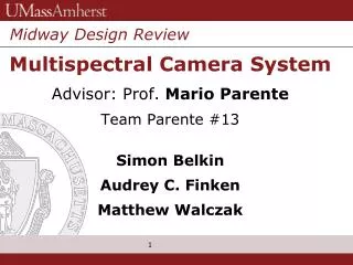
Midway Design Review Multispectral Camera System Advisor: Prof. Mario Parente Team Parente #13 Simon Belkin Audrey C. Finken Matthew Walczak
Presentation Overview • PDR Feedback • Refined Application • Constructing Camera System • Testing Components • Budget • Updated Timeline • Demo • Deliverables for CDR
PDR Feedback • Get a precision enclosure for camera system. • Determine an application for our camera system. • Check the web for connections of camera to the filter wheel assembly. • Get into the lab.
PDR Feedback - solutions • An enclosure system was not needed. C-Mount adapters provided a completely enclosed optical path. • Refined application of camera system: Agriculture imaging. • Utilized internet research in all aspects of multispectral camera design. • Utilized lab space for system integration.
Refined Application – Potential Uses • Determine crop conditions. • Visualize stress & yield improvement. • Grain evaluation & sorting. • Evaluate forest canopy and soil conditions. • Vegetation and vineyard analysis. • Weed infestation & disease detection.
Camera & Lens Demo Resistor Image Captured; Notice Extreme Magnification Camera System with Resistor in Position to Image
Camera & Lens Demo Tip of a Small Screwdriver Showing Magnification Our Lens and Tube System. Tubes Lead to Magnification
Filter Wheel • We did testing on the filters provided to us. Through the use of a spectrometer, dark room, and a white light source, we were able to identify the different wavelength spectrums of these filters. • The graphs produced by the spectroscopic software shows the wavelength ranges of the filters.
Filters Filter wavelength: 440-455nm Filter wavelength: 505-525nm
Filters Cont. Filter wavelength: Clear filter Filter wavelength: 420-440nm
Building the System – Stepper Motor • Our stepper motor consists of a 2 stationary coils and these are turned on and pull a rotary magnet towards the coil. This action turns a shaft. • But you must turn the coils on and off at the right moment to create rotary movement. This requires an external circuit consisting of pulses and these pulses must contain voltage and current to deliver energy to the stepper motor.
Test and Evaluation Stepper Motor Hall Effect Sensor (not in used) Pin-Out
Basic Test for Stepper Motor • This was a basic test to check that the Stepper motor work. By turning the motor manually we provided feedback voltage which lit the LEDs. • Similarly we used a Back EMF test in which you short two leads together and if the motor was difficult to move the connections were from the same phase.
Issues with Filter/Stepper Motor • The main issue with the Filter wheel was the stepper motor. • We tried using different ways to excite the stepper motor to get it to turn however, we were unsuccessful. • We have prove through different methods the pin out and that the stepper motor is functional.
Additional Testing • As an alternate we tried using a Arduino for testing purposes. Having found possible set ups for a 4 wire stepper motor we tried basic code that would excite one pin at a time while setting the other to low to test our stepper motor. • This however also proved inconclusive.
Using Various Arduino Code to Test • As an alternate we also tried using an L298 as recommended by some sources we found. This device would act as H-Bridge (a circuit that enables a voltage to be a applied across a load in either direction). Similarly without result. • Another group also recommended using a ULN2803A Darlington Array (which takes current amplified by the first transistor is amplified further by the second one) with a basic Arduino code. Similarly with out results.
Building the System – Raspberry Pi • Credit size Linux machine • SD card for storage • Ethernet Port • General Programming Input Output • To control stepper motor • Low cost
Control of the Stepper motor using RPi • Coding on RPi • python • Use of a stepper driver • EasyDriver stepper from SparkFun • to prevent damage to filter wheel due to high current supplied from the RPi. • Allow an easier control of stepping
Issues with Microcontroller • RPi • Arrival of stepper driver caused delay • Misconnection of RPi • Switched to Arduino board • Stepper motor didn’t turn • Couldn’t pinpoint source of error
Building the System – Issues found • Requested parts had been delayed in the ordering process. (Set us back in time). • Optical path needed more components to correct an issue. (Set us back in time and money). • Connections – can’t connect to monitors in SDP lab • Filter wheel and stepper motor driver issue.
Analysis of Project progress • Have all the components for the optics. Integrate system is in progress. • Control of the filter wheel turning with and without Rpi • Camera is able to work on the RPi
MDR goals • Control of filter wheel motor • Integrate the system • In progress just missing an equipment • Camera able to take pictures
Filters We Have and Need • 1) 420-440nm {‘filter 6’} • 2) 440-455nm {‘filter 2’} • 3) 510-520nm {‘filter 5’} • 4) 400-650nm {‘IR-Cut filter’} • 5) Need additional in range 450-510nm • 6) Need additional filters in range of 700-1000nm
Deliverables for CDR • Have the system built and be able to take pictures • We would have a solution to deal with aberrations • Full control of stepper motor
Conclusion We spent a lot of time researching and gathering info this semester and we also encountered difficulties and delays that prevented us from meeting our MDR goals. But we have learned from our experience/mistakes and will be better prepared next semester and meet our set goals.