Download
1 / 30
300 likes | 320 Views
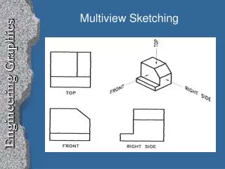
Unit 5 Shap Description (Orthographic Projection). نظرية الأسقاط. Even simple, primitive shapes often need several views to fully describe their topology.

E N D
Unit 5 Shap Description (Orthographic Projection) نظرية الأسقاط
Even simple, primitive shapes often need several views to fully describe their topology.
Holes and cylinders may appear “True Shape and Size” (TSS), or foreshortened depending on the view in which they appear. (Foreshortened circles will appear as ellipses.)
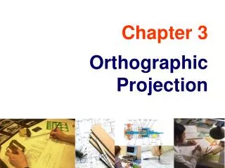
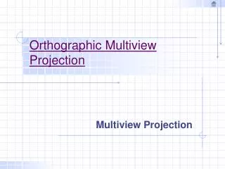
Orthographic Projection • Orthographic projection (sometimes referred to as multi-view projection), is a geometric procedure used in the engineering disciplines to project multiple graphic images of three-dimensional objects, onto a single two-dimensional plane. The procedure is also called engineering drawing or drafting, and is the primary means of communication used by designers and engineers in the design process. • Multiple views in an orthogonal orientation (each rotated 90º from the other), is fundamental to the definition of feature and part characteristics such as size, location, orientation, and functional relationships. • The object can only be viewed from the front, top, right side, left side, back, or bottom. With the images indelibly fixed on the planes, and the box unfolded, the projected images or views would always be oriented orthographically, and aligned with each other, from view to view on the drawing.
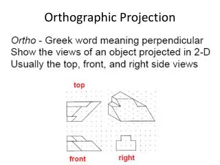
Ortho means “at 90 degrees”, and is a form of parallel projection. Orthographic projections are used to show several views of the same object in one drawing set.
Orthographic Projection Theory Observation of an object begins with the direction from which the object is to be viewed—the line of sight.
Orthographic Projection Theory The viewing station for the observer is always an infinite distance from the object. Viewing Station at Infinity
Orthographic Projection Theory The plane of projection is located between the viewing station and the object (third angle projection). Line of Sight Viewing Station at Infinity Projection Plane (Picture Plane Viewing Plane)
Orthographic Projection Theory The line of sight is always normal to the plane of projection Line of Sight Viewing Station at Infinity Projection Plane (Picture Plane Viewing Plane)
Orthographic Projection Theory Object The object may be located anywhere behind the plane of projection Line of Sight Viewing Station at Infinity Projection Plane (Picture Plane Viewing Plane)
Orthographic Projection Theory Object Because the observation location is at infinity, parallel visual rays extend from the object to the plane of projection, and produce the image on the projection plane. Line of Sight Viewing Station at Infinity Parallel Visual Rays Projection Plane (Picture Plane Viewing Plane)
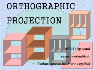
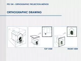
The glass box concept theorizes that an object is suspended inside a six-sided glass cube (notice the use of hidden lines on the glass box, depicting lines that would not be visible from the given perspective).
As the object is viewed from a specific orientation (perpendicular to one of the sides of the cube) visual rays project from the object to the projection plane. These projectors are always parallel to each other.
The object’s image is formed on the Frontal projection plane by the pierce points of the visual rays.
The process is repeated to construct the right side view on the profile plane
Similarly, the top view is projected to the horizontal plane
For many three-dimensional objects, two to three orthographic views are sufficient to describe their geometry.
The box can be unfolded to show the multiple views in a single x-y plane
Because the observation point is located at infinity, the integrity of feature size and location are maintained, and the views are oriented orthogonally in relationship to each other. TOP RIGHT SIDE FRONT
TOP RIGHT SIDE FRONT Notice that the projectors or extension lines, are perpendicular to the folding lines of the glass box. (Fold lines and extension lines are drawn very lightly, when used, and are not part of the finished drawing.)
Dimensional Data Can then be added to the drawing Notice the three basic line types: • Solid – A Visible Edge • Hidden - An Invisible Edge • Center – Center of a Cylinder (Internal or External)
The Glass Box Concept Click on image to animate - click outside for next slide
Height = h Width = w Depth = d Directional Orientation in Orthographic Projection TOP d Two or three views of a 3-dimensional object are often sufficient for a complete definition of part geometry. Width and depth are displayed in the top view; height and width in the front view, height and depth in the side view. w FRONT RIGHT SIDE w d h h
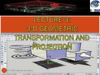
DIRECTION AND ORIENTATION INORTHOGRAPHIC PROJECTION(PRINCIPAL PROJECTION PLANES)
Projection methods: 3RDAngle (US Standard) ISO (1ST Angle Metric Standard) NOTE: Reverse construction methods work just as well in 1ST Angle projection.
Third-angle Projection First-angle Projection 1st angle and 3rd angle Orthographics... The difference: