Understanding Circuits: Deriving Equations and Graphing Voltage Changes
Delve into circuit models to analyze voltage changes, graph equations, and explore the impact of resistors and capacitors on signal processing. Gain insight into Kirchoff’s laws and RC response behaviors.

Understanding Circuits: Deriving Equations and Graphing Voltage Changes
E N D
Presentation Transcript
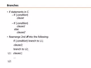
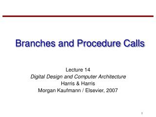
CIRCUITS, NODES, AND BRANCHES • Last time: • Looked at circuit elements, used to model the insides of logic gates • Saw how the resistor and capacitor in the gate circuit model make the change in output voltage gradual • Looked at the mathematical equations that describe the output voltage • Today: • Derive the mathematical equation for the change in gate output voltage • Practice an easy method used to graph and write the equation for the changing output voltage • Look at how R and C affect the rate of change in output voltage • Look at how R and C affect how quickly we can put new signals through • Review ideas we will need to understand Kirchoff’s laws
RC RESPONSE R Internal Model of Logic Gate V V out in C Behavior of Vout after change in Vin Vout Vout Vin Vout(t=0) Vout(t=0) Vin 0 0 time 0 time 0
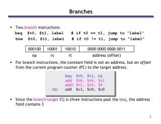
RC RESPONSE We said that Vout(t) has the general exponential form Vout(t) = A + Be-t/t Initial value Vout(t=0) = A + B Final value Vout(t→∞) = A But we know Vout(t→∞) = Vin so rewrite Vout(t) = Vin + [Vout(t=0)-Vin]e-t/t t = RC We will now prove that time constant t is Remember, Vout(t) has gone 63% of the way from initial to final value after 1 time constant.
R V V out in i C i R C RC RESPONSE: Proof of Vout equation
RC RESPONSE: Proof We know Vout(t) = Vin + [Vout(t=0)-Vin]e-t/RC Is a solution? Substitute: This is the solution since it has the correct initial condition!
R Input node Output node Vout + Vin C - ground Vin 10 Vout 6.3V 0 time 0 1nsec Example: Draw graph and write equation Assume Vin has been zero for a long time, and steps up to 10 V at t=0. Assume R = 1KΩ, C = 1pF . Ingredients for graph: • Initial value of Vout is 0 • Final value of Vout is Vin=10V • Time constant RC is 10-9 sec • Vout reaches 0.63 X 10 in 10-9 sec Ingredients for equation: Vout(t) = 10 - 10e-t/1nsec Vout(t) = Vin + [Vout(t=0)-Vin]e-t/RC =>
R Input node Output node Vout + C Vin - ground Charging and discharging in RC Circuits(The official EE40 Easy Method) Method of solving for any node voltage in a single capacitor circuit. 1) Simplify the circuit so it looks like one resistor, a source, and a capacitor (it will take another two weeks to learn all the tricks to do this.) But then the circuit looks like this: 2) The time constant is t = RC. 3) Find the capacitor voltage before the input voltage changes. This is the initial value for the output, Vout(t=0). 4) Find the asymptotic value Vout(t→∞), in this case, equals Vin after step 5) Sketch the transient period. After one time constant, the graph has passed 63% of the way from initial to final value. 6) Write the equation by inspection.
Vin Vin Vout Vout 0 0 time time 0 0 PULSE DISTORTION What if I want to step up the input, wait for the output to respond, then bring the input back down for a different response? Vin 0 time 0
6 6 6 PW = 0.1RC PW = RC PW = 10RC O + 5 5 5 4 4 4 Vin Vout Vout Vout - 3 3 3 2 2 2 1 1 1 0 0 0 0 0 1 5 2 10 3 15 4 20 25 5 0 1 2 3 4 5 Time Time Time PULSE DISTORTION The pulse width (PW) must be greater than RC to avoid severe pulse distortion.
EXAMPLE R Suppose a voltage pulse of width 5 ms and height 4 V is applied to the input of the circuit at the right. Sketch the output voltage. V V out in C R = 2.5 KΩ C = 1 nF First, the output voltage will increase to approach the 4 V input, following the exponential form. When the input goes back down, the output voltage will decrease back to zero, again following exponential form. How far will it increase? Time constant = RC = 2.5 ms The output increases for 5ms or 2 time constants. It reaches 1-e-2 or 86% of the final value. 0.86 x 4 V = 3.44 V is the peak value.
4 3.5 3 2.5 2 1.5 1 0.5 0 0 2 4 6 8 10 EXAMPLE Just for fun, the equation for the output is: { 4-4e-t/2ms for 0 ≤ t ≤5 ms 3.44e-(t-5ms)/2.5ms for t > 5 ms Vout(t) =
Now we can find “propagation delay” tp; the time between the input reaching 50% of its final value and the output to reaching 50% of final value. Today’s case, using “perfect input” (50% reached at t=0): 0.5 = e-tp tp = - ln 0.5 = 0.69 It takes 0.69 time constants, or 0.69 RC. We can find the time it takes for the output to reach other desired levels. For example, we can find the time required for the output to go from 0 V to the minimum voltage level for logic 1. Knowing these delays helps us design clocked circuits. APPLICATIONS
Adding Voltages in Series In electrical engineering we generally add voltage drops. Example: • Go around the path that comprises Vx. Start at + terminal, • end at – terminal. • Look at the first sign you encounter at each element. • If +, add that voltage. If -, subtract. • 3. The final sum is Vx. + 5 – 8 – 6 + 8 = -1 And that’s OK!
In the last slide, we “guessed Vx wrong”; the bottom end was actually higher potential than the top. WE DON’T CARE! If I need to find a voltage or current, I just give it a name and write down a polarity/direction. Whatever I feel like at the time. Then I solve for the unknown. If the voltage/current “doesn’t really go that way”, the answer will be negative. SO WHAT. Just remember how to flip things if you need to: JUST PICK A POLARITY Ix - Vx + + -Vx - Same Thing! -Ix
We only need to worry about associated reference currents in 3 situations (here we need to have associated reference current): Using Ohm’s law in a resistor Using I = C dV/dt in a capacitor Calculating power P=VI @#%*ING ASSOCIATED REFERENCE CURRENTS I + V - Otherwise, forget about it! Work with currents and voltage in whatever direction you want!