Download
1 / 29
470 likes | 1.07k Views
Two Phase Flow Modeling – PE 571 Chapter 3: Slug Flow Modeling Dukler and Hubbard – Horizontal Pipes. Dukler and Hubbard Model (1975). Introduction. Dukler and Hubbard Model (1975). Introduction. Slug flow occurs in horizontal, inclined, and vertical pipes.

E N D
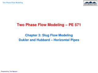
Two Phase Flow Modeling – PE 571 Chapter 3: Slug Flow Modeling Dukler and Hubbard – Horizontal Pipes
Dukler and Hubbard Model (1975) Introduction
Dukler and Hubbard Model (1975) Introduction Slug flow occurs in horizontal, inclined, and vertical pipes. SF and elongated bubble flow belong to the intermittent pattern. SF Characterized by an alternating flow of gas pockets and liquid slugs. The large gas pockets are called Taylor bubbles. The slugs are liquid which contains small entrained gas bubbles
Dukler and Hubbard Model (1975) Introduction LU: Unit length of the slug LS, LF: Length of the slug and the liquid film vTB: translational velocity vLLS and vGLS: velolities of liquid and gas phase in the slug body. vLTB and vGTB: liquid film and gas-pocket velocity in the stratified region vTB > vLLS > vGLS > vLTB > vGTB
Dukler and Hubbard Model (1975) Mechanism of Slug Flow Liquid slugs bridge the entire pipe cross-sectional area. They move at relatively high velocity (close to the mixture velocity) and overruns the slow moving film ahead of it, picks it up and accelerates it to the slug velocity creating a turbulent mixing zone in the front of the slug. At the same time, the gas pocket pushes into the slug, causing the slug to shed liquid from its back creating the film region. For steady state flow, the rate of pickup is equal to the rate of shedding.
Dukler and Hubbard Model (1975) Input and Output Parameters us and HLLS are the slug frequency and the liquid holdup in the slug body. Assuming homogeneous no-slip model flow occurs in the slug body.
Dukler and Hubbard Model (1975) Total Pressure Drop in a Slug Unit The total pressure drop across a slug unit consists of two components: Accelerational pressure drop in the mixing zone: due to Dv: slug and liquid film Frictional pressure drop in the slug body: due to shear with the wall Pressure drop in the stratified region behind the slug is neglected. Total pressure drop gradient in a unit slug
Dukler and Hubbard Model (1975) Accelerational Pressure Drop The pickup rate x, (mass/time): is the rate of mass picked up by the slug body from the film zone. The force acting on the picked-up mass equals to the rate of change of momentum: F = x(vS - vLTBe) Hence, the pressure drop due to the acceleration is given
Dukler and Hubbard Model (1975) Frictional Pressure Drop This pressure drop is due to the shear between the moving slug body and the pipe wall. Note that the flow in the slug body is assumed to be homogeneous no-slip flow with a fully developed turbulent velocity profile.
Dukler and Hubbard Model (1975) Velocities of the slug vS is the slug velocity representing the mean velocity of the fluid in the slug body vTB is the translational velocity which is the front velocity of the slug.
Dukler and Hubbard Model (1975) Velocities of the slug vS is the slug velocity representing the mean velocity of the fluid in the slug body vTB is the translational velocity which is the front velocity of the slug.
Dukler and Hubbard Model (1975) Velocities of the slug The tractor moves at a velocity of vS, scooping the sand ahead of it. The sand is accumulated in the front of the scoop. The front of the scooped sand moves faster than vS. The front velocity of the sand is equal to the tractor velocity plus the volumetric-scooping rate divided by the cross-sectional area of the scoop. In other words, the translational velocity, vTB, is equal to the slug velocity, vS, plus the volumetric-scooping rate divided by the cross-sectional area of the slug (additional velocity gained by the pickup process).
Dukler and Hubbard Model (1975) Velocities of the slug Assuming that the total volumetric flow of the mixture is constant through any cross section of the pipe. Note that the total mass rate, WL + WG, is not constant at any cross section of the pipe because of the intermittent nature of the flow. qL + qG = constant
Dukler and Hubbard Model (1975) Velocities of the slug Choosing a coordinate system moving at the translationnal velocity, vTB, The continuity equation implies that the rate of pickup equals to the rate of shedding: Defining c as Therefore: vTB = vS + cvS = (1 + c)vS = cOvS.
Dukler and Hubbard Model (1975) Velocities of the slug The parameter c can be proved that it is a unique function of the Reynolds number ReLS. ReLS = rLvMd/mL. c = 0.021ln(ReLS) + 0.022
Dukler and Hubbard Model (1975) Hydrodynamics of the Film If we choose the interface of the slug as the coordinate, then The liquid will flow backwards in the slug body at a velocity of vTB – vS. The liquid film will flow backward with a velocity of vTB – vLTB. Note that the vF increases as the cross-sectional area of the film decreases.
Dukler and Hubbard Model (1975) Hydrodynamics of the Film The following analysis is carried out with an open channel flow. Assuming the pressure drop in the stratified region is neglected. The velocity of the liquid film:
Dukler and Hubbard Model (1975) Hydrodynamics of the Film Note that is the average hydrostatic pressure acting on a cross sectional area of the liquid film. Hence, the film profile is given
Dukler and Hubbard Model (1975) Hydrodynamics of the Film Where the shear stress force is given The equilibrium level, hE, occurs when The critical level, hC, occurs when
Dukler and Hubbard Model (1975) Slug Length The slug unit period, TU, is the time it takes for a slug unit to pass a given point in the pipe, is given by the inverse of the slug frequency, uS:
Dukler and Hubbard Model (1975) Slug Length There are two different ways to carry out the mass balance for a slug unit: Integration with space: “freezing” a slug unit at a given time and checking the liquid Integration with time: Integrating the amount of liquid passing through a cross sectional area of the pipe at a given point along the pipe. TF
Dukler and Hubbard Model (1975) Slug Length Definition of pickup rate and relationship between vTB and vS: vTB = vS + cvS = (1 + c)vS = cOvS. Combining these two equations and assuming equilibrium liquid film: HLTB = HLTBe. Let
Dukler and Hubbard Model (1975) Slug Length The mass balance equation by applying the integration with time give This is equation can be simplified by using the assumption: equilibrium liquid film. Combining with the correlation gives
Dukler and Hubbard Model (1975) Gas Pocket Velocity The gas pocket velocity can be obtained from a mass balance on the gas phase with using the translational velocity coordinate system between two planes: This eq. implies that the rate of pickup = the rate of shedding for gas phase. Hence
Dukler and Hubbard Model (1975) Length of Mixing Zone The length of the mixing zone is based on a correlation for the “velocity head” vH as follows
Dukler and Hubbard Model (1975) Calculation Procedure 1. Specify input parameters: WL, WG, d, fluid properties, HLLS and uS. 2. Calculate the slug velocity, vS: 3. Determine c: c = 0.021ln(ReLS) + 0.022 4. Assume a value for LS, calculate LF: 5. Integrate numerically Eq. below from z = 0 - L and find HLTB(z), vLTB(z), HLTBe, and vLTBe
Dukler and Hubbard Model (1975) Calculation Procedure 6. Calculate Ls from 7. Compare the assumed and calculated values of LS. If no convergence is reached, update LS and repeat steps 4 through 7 8. Once the convergence is reached, calculate the following outputs: LS, LF, LU, vS, vTB, vLTB(z), HLTB(z), and HLTBe vLTBe: from the final results of the integration - DpA from: ReS, fS, - DPF, - DpU, and –dp/dL
Dukler and Hubbard Model (1975) Calculation Procedure
Dukler and Hubbard Model (1975) Calculation Procedure