Download
1 / 15
150 likes | 164 Views
service repair manual

E N D
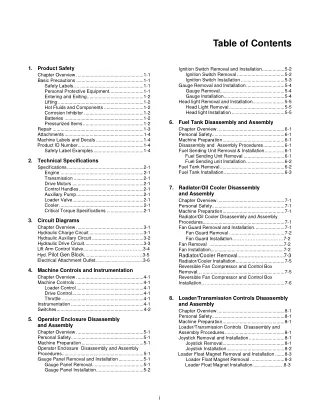
Table of Contents Ignition Switch Removal and Installation ................. 5-2 Ignition Switch Removal .................................... 5-2 Ignition Switch Installation ................................. 5-3 Gauge Removal and Installation ............................. 5-4 Gauge Removal ................................................. 5-4 Gauge Installation .............................................. 5-4 Head light Removal and Installation ........................ 5-5 Head Light Removal .......................................... 5-5 Head light Installation ........................................ 5-5 1. Product Safety Chapter Overview ................................................... 1-1 Basic Precautions ................................................... 1-1 Safety Labels…. ................................................ 1-1 Personal Protective Equipment .......................... 1-1 Entering and Exiting ........................................... 1-2 Lifting ................................................................. 1-2 Hot Fluids and Components .............................. 1-2 Corrosion Inhibitor ............................................. 1-2 Batteries ............................................................ 1-2 Pressurized Items .............................................. 1-2 Repair ..................................................................... 1-3 Attachments ............................................................ 1-4 Machine Labels and Decals .................................... 1-4 Product ID Number .................................................. 1-4 Safety Label Examples ...................................... 1-4 6. Fuel Tank Disassembly and Assembly Chapter Overview ................................................... 6-1 Personal Safety ....................................................... 6-1 Machine Preparation ............................................... 6-1 Disassembly and Assembly Procedures ................ 6-1 Fuel Sending Unit Removal & Installation ............... 6-1 Fuel Sending Unit Removal ............................... 6-1 Fuel Sending unit Installation ............................. 6-2 Fuel Tank Removal ................................................. 6-2 Fuel Tank Installation .............................................. 6-3 2. Technical Specifications Specifications .......................................................... 2-1 Engine ............................................................... 2-1 Transmission ..................................................... 2-1 Drive Motors ...................................................... 2-1 Control Handles ................................................. 2-1 Auxiliary Pump ................................................... 2-1 Loader Valve ...................................................... 2-1 Cooler ................................................................ 2-1 Critical Torque Specifications ............................ 2-1 7. Radiator/Oil Cooler Disassembly and Assembly Chapter Overview ................................................... 7-1 Personal Safety ....................................................... 7-1 Machine Preparation ............................................... 7-1 Radiator/Oil Cooler Disassembly and Assembly Procedures .............................................................. 7-1 Fan Guard Removal and Installation ....................... 7-1 Fan Guard Removal .......................................... 7-2 Fan Guard Installation…………………..……… .7-2 Fan Removal .........................................................7-2 Fan Installation........................................................7-2 Radiator/Cooler Removal................................7-3 Radiator/Cooler Installation ..................................... 7-5 Reversible Fan Compressor and Control Box Removal… .............................................................. 7-5 Reversible Fan Compressor and Control Box Installation… ........................................................... 7-6 3. Circuit Diagrams Chapter Overview ................................................... 3-1 Hydraulic Charge Circuit ......................................... 3-1 Hydraulic Auxiliary Circuit ....................................... 3-2 Hydraulic Drive Circuit ............................................. 3-3 Lift Arm Control Valve..............……………………...3-4 Hyd. Pilot Gen Block................……………………3-5 Electrical Attachment Outlet.........................................3-6 4. Machine Controls and Instrumentation Chapter Overview ................................................... 4-1 Machine Controls .................................................... 4-1 Loader Control ................................................... 4-1 Drive Control ...................................................... 4-1 Throttle .............................................................. 4-1 Instrumentation ....................................................... 4-1 Switches .................................................................. 4-2 8. Loader/Transmission Controls Disassembly and Assembly Chapter Overview ................................................... 8-1 Personal Safety ....................................................... 8-1 Machine Preparation ............................................... 8-1 Loader/Transmission Controls Disassembly and Assembly Procedures ............................................. 8-1 Joystick Removal and Installation ........................... 8-1 Joystick Removal ............................................... 8-1 Joystick Installation ............................................ 8-2 Loader Float Magnet Removal and Installation ....... 8-3 Loader Float Magnet Removal .......................... 8-3 Loader Float Magnet Installation...........................8-3 5. Operator Enclosure Disassembly and Assembly Chapter Overview ................................................... 5-1 Personal Safety ....................................................... 5-1 Machine Preparation ............................................... 5-1 Operator Enclosure Disassembly and Assembly Procedures .............................................................. 5-1 Gauge Panel Removal and Installation ................... 5-1 Gauge Panel Removal ....................................... 5-1 Gauge Panel Installation .................................... 5-2 i
Rubber Track Loader Table of Contents Cab Filtration ....................................................... 11-22 Fan Cleaning ...................................................... 11-22 Maintenance Schedule ........................................ 11-23 12. Lubricant & Fuel Specifications Specifications ........................................................ 12-1 9. Hydrostatic & Aux. Pump Disassembly and Assembly Chapter Overview ................................................... 9-1 Personal Safety ....................................................... 9-1 Machine Preparation ............................................... 9-1 Hydrostatic & Hydraulic Pump Disassembly and Assembly Procedures ...................................... 9-1 Charge Pump Removal ........................................... 9-1 Auxiliary Pump Removal ......................................... 9-3 Auxiliary Pump Installation ...................................... 9-4 Tandem Pump Removal .......................................... 9-4 Tandem Pump Installation ....................................... 9-5 Hydraulic Reservoir Clean out..................................... 9-5 13. Troubleshooting Chapter Overview ................................................. 13-1 Personal Safety ..................................................... 13-1 Machine Preparation ............................................. 13-1 Preliminary Checkout ............................................ 13-1 Visual Inspection ............................................. 13-1 Troubleshooting Scenarios………………………...13-2 14. Hydraulic Pressure (Check & Adjustment) Chapter Overview ................................................. 14-1 Personal Safety ..................................................... 14-1 Charge Pressure Check & Adjustment ................. 14-1 Auxiliary Pressure Check & Adjustment…..………14-3 High Flow Troubleshooting.…………....…………..14-4 Low Flow Troubleshooting .................................... 14-4 Lift Arm Pressure Check..……………..……………14-4 Drive Pressure Check & Troubleshooting……..….14-5 Posi-Power Pressure Check & Adjustment.….…..14-6 15. Hydraulic Cylinder & Loader Valve Chapter Overview ................................................. 15-1 Personal Safety ..................................................... 15-1 Disassembly & Assembly ...................................... 15-1 Hydraulic Cylinder Disassembly ............................ 15-1 Hydraulic Cylinder Assembly ................................ 15-3 Loader Valve Disassembly.................................... 15-4 Loader Valve Assembly ........................................ 15-4 10. Undercarriage Disassembly and Assembly Chapter Overview ................................................. 10-1 Personal Safety ..................................................... 10-1 Machine Preparation ............................................. 10-1 Undercarriage Disassembly and Assembly Procedures ............................................................ 10-1 Sprocket Removal and installation ........................ 10-1 Sprocket Removal ............................................ 10-1 Sprocket Installation ......................................... 10-3 Drive Motor Removal ............................................. 10-3 Drive Motor Installation .......................................... 10-4 Wheel Replacement....................................................10-4 Wheel Installation….....................................................10-5 14" Wheel Keeper Plates......................................…..10-5 11. Maintenance Chapter Overview ................................................. 11-1 Personal Safety ..................................................... 11-1 Air Cleaner ............................................................ 11-1 Grease Fittings ...................................................... 11-3 Undercarriages ...................................................... 11-3 Track Tension........................................................ 11-3 Drive Sprocket Rollers ........................................... 11-4 Tilt-Up Canopy ...................................................... 11-5 Jacking Procedure ................................................. 11-6 Lift Arm Brace ...................................................... 11-7 Track Removal ...................................................... 11-8 Track Installation ................................................... 11-9 Engine Oil & Filter ............................................... 11-11 Engine Oil Specifications .................................... 11-13 Engine Oil Level Check ....................................... 11-13 Hydraulic Fluid & Filter ....................................... 11-14 Fuel Filter ............................................................ 11-15 Case Drain Filter ................................................. 11-15 Hydraulic Reservoir (Cleanout) ........................... 11-15 Water Separator .................................................. 11-16 Fuse Panel .......................................................... 11-16 Drive Belt Tension Check .................................... 11-17 Drive Belt Tension Adjustment ............................ 11-17 Drive Belt Removal ............................................ 11-18 Drive Belt Installation ........................................... 11-18 Radiator/Oil Cooler Cleaning ............................... 11-19 Chassis & Engine Cleaning ................................. 11-19 Extreme Conditions ............................................. 11-20 Cooler Air Flow Test ........................................... 11-20 ii
1. Product Safety Chapter Overview This chapter contains product safety information for the Terex PT-100 Forestry Compact Track Loaders. Read and understand all product safety information before attempting to service any Compact Track Loader. The person(s) in charge of servicing a Compact Track Loader may be unfamiliar with many of the systems on the machine. This makes it especially important to use caution when performing service tasks. Familiarize yourself with the affected system(s) and components before attempting any type of maintenance or service. Safety Alert Symbol This symbol means: Attention! Be alert! Your safety is involved! It is not possible to anticipate every potential haz- ard. The safety messages included in this docu- ment and displayed on the machine are not all- inclusive. They are intended to make you aware of potential risks and encourage a safe approach to performing service work. If you use a tool, proce- dure, work method or operating technique that is not specifically recommended by Terex, you must satisfy yourself that it is safe for you and others. You must also ensure that the machine will not be damaged or be made unsafe by the operation, lubrication, maintenance or repair procedures that you choose. The safety alert symbol is used to alert you to potential personal injury hazards. Obey all safety messages that follow this symbol to avoid possible injury or death. This symbol is used as an attention-getting device throughout this manual as well as on decals and labels fixed to the machinery to assist in potential hazard recognition and prevention. Property or equipment damage warnings in this publi- cation are identified by the signal word "NOTICE". NOTICE Basic Precautions Safety Labels Safety labels have been included and are displayed in various places throughout the machine to serve as warnings of potentially dangerous conditions. Read and understand all "Safety" labels on any Compact Track Loader before attempting to operate, maintain or repair it. Replace any damaged, illegible or missing labels immediately, prior to service. “NOTICE” Indicates a hazardous situation which, if not avoided, could result in property or equip- ment damage. The word “Note” is used throughout this manual to draw your attention to specific topics or to supplement the information provided in that section. Improper or incomplete maintenance/repair of a Compact Track Loader can be dangerous and may result in machine damage, injury or death. Do not attempt to perform any type of repair or main- tenance on a Compact Track Loader until you have read and fully understood both this manual and the machine specific operation and maintenance manual. Refer to the Operation and Maintenance manual for instructions regarding proper machine operation and maintenance techniques before operating or servicing any Compact Track Loader. Personal Protective Equipment Personal protection equipment is recommended when performing maintenance or service on a machine. Always wear appropriate protective equipment for working conditions when working on or around the machine. Loose clothing should not be worn and long hair should be restrained. Wear hard hats, protective face/eyewear, safety shoes and any other equipment necessary to ensure your safety and the safety of oth- ers around you as you work. 1-1
Compact Track Loader 1. Product Safety Entering and Exiting Always use steps and handholds when entering or exiting a Compact Track Loader. Clean any mud or debris from steps or work platforms before using them. Always face the machine when using steps and hand- holds. When it is not possible to use the designed entry/exit system, utilize ladders, scaffolds, or work platforms to safely gain access to the machine. Pressurized Items 1. Do not use hands or any other body part to check for fluid leaks in the hydraulic system. Always use a solid material like wood or metal to check for this type of leak. Leaking fluid under pressure can pen- etrate body tissue. Fluid penetration can cause serious injury and even death. If fluid is injected into your skin, get treatment immediately. Seek treatment from a doctor that is familiar with this type of injury. Lifting Use a hoist when lifting components that weigh 50 lb (23 kg) or more, to avoid back injury. Make sure all chains, hooks, slings, etc., are in good condition and are of the correct capacity. Be sure hooks are posi- tioned correctly and equipped with a spring latch. Lifting eyes are not to be side loaded during a lifting operation. 2. Relieve pressure from the hydraulic system before disconnecting or removing any lines, fittings or related items. Do this by relaxing all hydraulic actuators. If the lift arms are raised, make sure they are securely braced. Be alert for possible pressure release when disconnecting any device from a pressurized system. Hot Fluids and Components Stay clear of hot components and system fluids of the engine, exhaust, radiator/oil cooler and hydraulic lines/tubes. Also, use caution when removing fill caps, breathers and plugs on the machine. Hold a rag over the cap or plug to prevent being sprayed or splashed by liquids under pressure. Be especially careful if the machine has been operated recently, fluids may still be hot. To ensure your safety, allow the machine to cool before attempting any service procedure that involves hot fluids or components. 3. Lower the lift arms before performing any work on the machine. If this cannot be done, make sure they are securely braced to prevent them from dropping unexpectedly during service. 4. Loose or damaged fuel, oil, hydraulic, lines, tubes and hoses can cause fires. Do not bend or strike high pressure lines or install ones that have been bent or damaged. Check lines, tubes and hoses carefully. See item 1 for precautions on checking for fluid leaks. Corrosion Inhibitor Corrosion inhibitor contains alkali. Avoid contact with eyes. Avoid prolonged or repeated contact with skin. Do not take internally. In case of contact, wash skin immediately with soap and water. For eyes, flush with large amounts of water for at least 15 minutes. Call Physician. Keep out of reach of children. 5. Pressurized air or water can also cause injury. When pressurized air or water is used for clean- ing, wear a protective face shield, protective cloth- ing, and protective shoes. The recommended max- imum air pressure for cleaning purposes is 30 psi (205 kPA). When using a pressure washer, keep in mind that nozzle pressures are typically very high. Generally, pressures are well above 2000 psi (13790 kPa). Follow all recommended practices provided by the pressure washer manufacturer. Batteries Do not smoke when inspecting the battery electrolyte level. Never disconnect any charging unit circuit or bat- tery circuit cable from the battery when the charging unit is operating. A spark can cause an explosion from the flammable vapor mixture of hydrogen and oxygen that is released from the electrolyte through the battery outlets. Do not let electrolyte solution make contact with skin or eyes. Electrolyte solution is an acid. In case of contact, immediately wash skin with soap and water. For eyes, flush with large amounts of water for at least 15 minutes. Call Physician. Keep out of reach of children. 1-2
Compact Track Loader 1. Product Safety Repair 8. Be prepared to stop an engine if it has been re- cently overhauled or the fuel system has been recently serviced. If the engine has not been assembled correctly, or if the fuel settings are not correct, the engine can possibly overspeed and cause bodily injury, death or property damage. Be prepared to shut off the fuel and air supply to the engine in order to stop the engine. Accidental machine starting can cause injury or even death to personnel working on a Compact Track Loader. As a precaution, disconnect the battery cables from the battery terminals, tape the battery clamps and remove the key from the ignition switch prior to per- forming any service work on a Compact Track Loader. Place a “Do Not Operate” tag prominently on the machine to inform personnel that the machine is being serviced. 9. Be careful when removing cover plates. Gradually back off the last two bolts or nuts located on oppo- site sides of the cover. Then, pry the cover loose to relieve any spring or other pressure before removing the last two nuts or bolts completely. 1. Disconnect the battery and discharge any capaci- tor before beginning work on a machine. Attach a Do Not Operate tag in the cab to alert any opera- tor that service is in progress. 10. Repairs requiring welding should be performed only by personnel adequately trained and knowl- edgeable in welding procedures and with the guid- ance of appropriate reference information. Determine the type of metal being welded and select the correct welding procedure and filler material to provide a weld that is as strong or stronger than the original weld. 2. If possible, make all repairs with the machine parked on a level, hard surface. Use blocks to pre- vent the machine from rolling while working on or under the machine. 3. Do not work on or under any machine that is sup- ported only by a hydraulic jack or hoist. Always use some sort of mechanical support to ensure that the machine will not fall. Terex jack stands work well to support the machine while performing maintenance or repair work. 11. Take precautions to avoid damaging wiring during removal and installation operations. Carefully route wires so that they will not contact sharp corners, objects or hot surfaces during operation. 12. When performing service that requires the lift arms to be in the raised position, always utilize the lift arm brace located on the rear of the loader tower. 4. Make sure the work area around the machine is safe and make yourself aware of any hazardous conditions that may exist. If the engine needs to be started inside an enclosure, make sure that the engine’s exhaust is properly vented. 13. Relieve hydraulic system pressure by relaxing all hydraulic actuators prior to attempting any hydraulic maintenance or repair. 5. Be sure all protective devices including guards and shields are properly installed and functioning cor- rectly before beginning any service task. If a guard or shield must be removed to perform the repair work, use extra caution. 14. Always tighten connections to the correct torque specification. Make sure that all shields, clamps and guards are installed correctly to avoid exces- sive heat, vibration or unwanted contact between parts during operation. Shields that protect exhaust components from oil spray in event of a line, tube or seal failure must be correctly installed. 6. Always use the appropriate tools for the work to be performed. Tools should be in good condition and you should understand how to use them properly before performing any service work. 15. Do not operate a machine if any rotating part is damaged or contacts other parts during operation. Any high speed rotating component that has been damaged or altered should be checked for balance before reusing. Make sure all protective devices, including guards and shields, are properly installed and functioning correctly before starting the engine or operating the machine. 7. When replacing fasteners, use parts of equivalent grade and size. Do not use a lesser quality fasten- er if replacements are necessary. 1-3
Compact Track Loader 1. Product Safety Attachments Only use attachments that are recommended by Terex. Safety Label Examples Examples of the labels and decals displayed on the machine are shown on this page. ??????? Make sure that all necessary guards and protective equipment are in place and functioning prior to operat- ing any attachment. WARNING Wear protective glasses and protective equipment as required by conditions or as recommended in the attachment’s operation manual. Crush Hazard Death or serious injury can result from contact with moving lift arm or attachment. Keep clear of lift arms and attachments. When replacement parts are required for your machine, use only genuine Terex replacement parts or parts that meet or exceed original specifications including, but not limited to physical dimensions, type, strength and material. Installing lesser components can lead to premature failures, product damage, personal injury or death. ??????? CRUSH HAZARD Contact with moving machine can result in death or serious injury. Keep clear of moving machine. 2030-593 WARNING ??????? Ensure that all personnel are far enough away from the work area so they will not be struck by flying ob- jects. Stay clear of the cutting edges, pinching surfaces or crushing surfaces of the attachment while performing any attachment maintenance, testing or adjustments. Fall Hazard Use the provided access system when entering or exiting the machine. Serious injury or death can result from falling. WARNING ??????? Machine Labels and Decals Labels and decals placed on the machine provide safety information and operating instructions. Familiarize yourself with the location and significance of these labels to ensure your safety. Crush Hazard Death or serious injury can result from contact with moving lift arm or attachment. Install lift arm brace prior to servicing. ??????? Product Identification Number The Product Identification Number (PIN) is located on the front of the left joystick tower (figure 1-1). Always provide the PIN when contacting the dealer about parts, service, warranty or accessories. No warranty claims will be processed unless the PIN is provided. Keep away from fan and belt while the engine is running. Stop engine before servicing. Entanglement Hazard Rotating parts can cause personal injury. ??????? Allow the machine to cool thoroughly before opening. Burn Hazard Hot fluid under pressure can scald. 2030-595 NOTICE 1-1 Read Operator’s manual Keep engine, exhaust and chassis areas free of debris. Fire Hazard Flammable debris can collect near hot components and lead to a fire. 1-4
Compact Track Loader 1. Product Safety ?????? ??????? WARNING ??????? WARNING ??????? Explosion/Burn Hazard Will cause death, burns or blindness due to ignition of explosive gasses or contact with corrosive acid. Fall Hazard Burn Hazard Crush Hazard Falling can result in serious injury or death. Contact with hot surfaces can cause burns. Rollover can crush and result in serious injury or death. Do not use the bucket/attachment as a work platform. Fasten Seat Belt • Keep all flames/sparks away! No Smoking! Read and understand all manuals prior to operation. • Do not touch hot components! Allow the machine to cool thoroughly prior to servicing. WARNING ??????? WARNING ??????? WARNING ??????? • • • 2030-601 2030-603 Rollover/Ejection Hazard Serious injury or death can result. Improper operation or maintenance can re- sult in serious injury or death. Fall Hazard Falling from a machine can result in serious injury or death. Read Operator’s Manual Read and understand the operator’s manual and all safety signs prior to operating or maintaining the machine. Carry loads low. Load unload and turn on level ground. Travel on inclines with heaviest end of machine uphill. No Riders WARNING ??????? • Relieve internal pressure before disconnecting any line or fitting. Keep away from leaks or pinholes. Use cardboard to check for leaks. Fluid injected into skin must be surgi- cally removed within a few hours by a doctor familiar with this type of injury or gangrene will result. • • Injection Hazard Escaping fluid under pressure can penetrate skin, causing serious injury. 1-5
2. Technical Specifications PT-100 Forestry Specifications Engine − Model: Perkins 1104C-44T (Turbo) − Displacement: 4.4 liter − Gross horsepower: 99.9 hp (74.5 kW) − Torque: 304 lb-ft. (412 Nm) − Idle rpm: 1000 (low idle), 2300 (high idle) − Average water /thermostat temperature: 190°F, 87.8°C Transmission − Model: A22VG tandem (Rexroth) Drive pumps Loader Valve − Make: Husco − Type: Load Sense Cooler − Operating pressure: 150 psi (1034 kPa) − Bypass relief pressure: 80 psi (689 kPa) − Hot oil sending unit: 225°F (107.2°C) Critical Torque Specs − Transmission Mounting Bolts o 85 ft-lb. (230.5 Nm) w/Blue Loctite − Drive Sprocket Drive Teeth Bolts o 85 ft-lb. (230.5 Nm) -Dry − Bogie Wheel Retaining Nuts (10’’) o 37 ft-lb. (100.3 Nm) -Dry − Bogie Wheel Retaining Nuts (14’’) o 37 ft-lb. (100.3 Nm) -Dry − Drive Sprocket Lug Nuts o 177 ft-lb. (480 Nm) -Dry − Drive Motor Mounting Bolts o 177ft-lbs. (480 Nm) -Dry − Displacement: 2.745 in3/rev (45 cc/rev) − Relief pressure: 5500 psi, 380 bar − Flow: 27.33 gpm (103.5 lpm) @ 2300 rpm Charge pump − Displacement: 1.587 in3/rev (26 cc/rev) − Relief pressure: 400-450 psi (2758-3102 kPa) 650 to 700 psi (4481.6-4826.3 kPa) at filter test port Drive Motors − Model: Rexroth MCR 5 (2-speed) − Displacement Low 50 in3/rev (820 cc/rev) − Displacement High 25 in3/rev (410 cc/rev) Control Handles − Model: 4TH6 (Rexroth) Auxiliary Pump − Make: Rexroth − Type: Axial Piston, Variable Load Sense − Displacement: 3.844 in3/rev (63 cc/rev) − Max Flow: 38 gpm (143.8 lpm) @ 2300 rpm − Relief pressure: 3300 psi (22,750 kPa) − Marginal Pressure: 362 psi (2,495 kPa) − Cooling/filtering: Oil is filtered and cooled at all times. In auxiliary mode, the oil is filtered af- ter the attachment to protect the machine if the attachment motor fails or contaminants are in- troduced from the quick couplers. 2-1
3. Circuit Diagrams Chapter Overview This chapter contains diagrams for the following PT- 100 Forestry circuits: hydraulic charge circuit, hydraulic auxiliary circuit, hydraulic drive circuit, loader valve, hydraulic pilot generation (solenoid) block and electri- cal attachment outlet. Hydraulic Charge Circuit Figure 3-1 PT-100 Forestry Hydraulic Charge Circuit 3-1
Compact Track Loader 3. Circuit Diagrams Hydraulic Auxiliary Circuit Figure 3-2 PT-100 Forestry Hydraulic Auxiliary Circuit 3-2
Compact Track Loader 3. Circuit Diagrams Hydraulic Drive Circuit Figure 3-3 PT-100 Forestry Hydraulic Drive Circuit 3-3
Compact Track Loader 3. Circuit Diagrams Lift Arm Control Valve Figure 3-4 PT-100 Forestry Lift Arm Control Valve 3-4
Compact Track Loader 3. Circuit Diagrams Hydraulic Pilot Generation Block Figure 3-5 PT-100 Forestry Pilot Generation Block 3-5
Thank you very much for your reading. Please Click Here. Then Get COMPLETE MANUAL. NO WAITING NOTE: If there is no response to click on the link above, please download the PDF document first and then click on it.
Compact Track Loader 3. Circuit Diagrams Electric Attachment Outlet Figure 3-6 PT-100 Forestry Electric Attachment Outlet 3-6