Download

1 / 28
280 likes | 313 Views
Learn about the objectives, operation, and benefits of Spanning Tree Protocol in ensuring network redundancy and reliability, avoiding broadcast storms and loop-free topologies.

E N D
Redundancy Redundant networking topologies are designed to ensure that networks continue to function in the presence of single points of failure.
Redundant Topologies • A goal of redundant topologies is to eliminate network outages caused by a single point of failure. • All networks need redundancy for enhanced reliability.
X sends to Y frame flooded frame flooded Y’s MAC address is not on the MAC address table Multiple Frame Transmissions
X sends to Y frame forwarded A and B incorrectly learn X’s MAC address on port 1 Y’s MAC address is not on the MAC address table Media Access Control Database Instability
Using Bridging Loops for Redundancy allow physical loops, but create a loop free logical topology
Spanning-Tree Protocol Data frames received on blocked links are dropped.
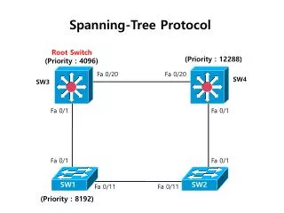
Spanning-Tree Protocol (STP): IEEE 802.1d • Selection of root bridge • Configurations are made by the other switches and bridges, using the root bridge as a reference point. • Each bridge or switch now determines which of its own ports offers the best path to the root bridge (root port). • The logical loop is removed by one of the switches or bridges by blocking the port that creates the logical loop. Blocking is done by calculating costs for each port in relation to the root bridge. Then the port with the highest cost is disabled.
A SpanningTree One Designated Port per segment. Through this port the segment has the minimum cost to the root bridge. The switch that has a designated port for some segment is the Designated Bridge for that segment.
Spanning-Tree Operation • One root bridge per network. • One root port per nonroot bridge. • One designated port per segment. • Nondesignated ports are unused. designated switch handles all communication from that LAN segment towards the root bridge.
Bridge Protocol Data Unit (BPDU) Bridge protocol data unit (BPDU)
Inferior BPDU When a switch first starts up, it assumes it is the root switch and sends BPDUs that contain the switch MAC address in both the root and sender BID.
BID=4 BID=13 BID=4 BID=21 BID=9 BID=21 BID=9 Electing the Root Bridge (1) No sending 7 BID=13 13 No sending 4 5 21 9 Each switch sendsBPDUs that contain the switch MAC address in both the Root and Sender BID.
Electing the Root Bridge (2) 4<7<13 5<13<21 7 13 9<21 4 5 21 9 4<9<21 A switch receiving the BPDU checks if the Root BID attached with BPDU is less than the Root BID it has recognized.
BID=4 BID=5 BID=5 Electing the Root Bridge (3) 7 13 4 5 BID=9 BID=4 21 9 If a new Root BID is found, the switch sends out a new BPDU containing the new Root BID to all ports except the one the new Root BID was received.
Electing the Root Bridge (4) 4<5<13 7 13 4<5<9 4 5 21 9 A switch receiving the BPDU checks if the Root BID attached with BPDU is less than the Root BID it has recognized.
Electing the Root Bridge (5) 7 BID=4 13 4 5 BID=4 21 9 All switches receive the BPDUs and determine that the switch with the lowest root BID value will be the root bridge.
Spanning-Tree Port States Ports can only receive BPDUs. Data frames are discarded and no addresses can be learned. Data is not forwarded, but MAC addresses are learned Determine if there are any other paths to the root bridge. For details go into Interactive Media Activity in 7.2.5
Spanning-Tree Recalculation A switched internetwork has converged when all the switch and bridge ports are in either the forwarding or blocked state (can take up to 50 secondswith 802.1d).
Rapid Spanning-Tree Protocol • The standard and protocol introduce the following: • Clarification of port states and roles • Definition of a set of link types that can go to forwarding state rapidly • Allowing switches, in a converged network, to generate their own BPDUs rather than relaying root bridge BPDUs
The blocking state of a port is renamed as the discarding state. The role of a discarding port is that of an alternate port. The discarding port can become the designated port if the designated port of the segment fails.
Rapid Spanning-Tree Port Designations Link types have been defined as point-to-point, edge-type, and shared. Point-to-point links and edge-type links can go to the forwarding state immediately. The Rapid SpanningTree Protocol, IEEE 802.1w, will eventually replace the SpanningTree Protocol, IEEE 802.1D.