Download
1 / 11
110 likes | 257 Views
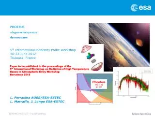
PHOEBUS a hypervelocity entry demonstrator 9 th International Planeraty Probe Workshop 18-22 June 2012 Toulouse, France L. Ferracina AOES/ESA-ESTEC L. Marraffa, J. Longo ESA-ESTEC. Paper to be published in the proceedings of the

E N D
PHOEBUSa hypervelocity entry demonstrator 9th International Planeraty Probe Workshop 18-22 June 2012 Toulouse, France L. Ferracina AOES/ESA-ESTEC L. Marraffa, J. Longo ESA-ESTEC Paper to be published in the proceedings of the 5th International Workshop on Radiation of High Temperature Gases in Atmospheric Entry Workshop Barcelona 2012 ESA UNCLASSIFIED – For Official Use
Outline Introducing PHOEBUS Project for a High-speed Of Entry Ballistic multi-User System • Technological objectives • Rationale • Relevance • Heritage An aerothermodynamics assessment • A parametric analysis of the re-entry phase • A non-equilibrium reacting CFD analysis… • …with radiation transport Final remarks
Technological Objectives • First ESA Demonstrator for high speed entry applications • Maturation and demonstration of critical technologies for: • Materials for Thermal Protection Systems (light ablators) • Aerothermodynamics Tools (uncertainties) • Entry Descent and Landing Systems • Concepts for crushable structures • Sensors for harsh environments • Data for design for demise • Data for space surveillance • Data for civil security • Radiation Data Base • Recovery operations…
Relevance • Useful for Science, Robotic Exploration and Human Space Flight Missions • Pathfinder for any sample return mission • Mastering technologies for hard landing • Mastering sensors for harsh environments • Crosslink contribution to • CleanSpace Program, Design for Demise • Surveillance of space (hypervelocity impact) • Civil security (hypervelocity entry) • SME’s role improvement (better positioning in the market)
Heritage • Preliminary cooperation with KAIST • 2 GSP (2008-2009) industrial phase A studies (TAS and AST primes, support from Makeev SRC) • Different solutions found (but feasibility with Volna established) • CDF study in Feb. 2011 • Four years development plan (Phase B/D) beginning of Phase B planned in 2012 • The Concurrent Design Facility (CDF) at ESA-ESTEC is an integrated design environment for interdisciplinary and inter-directorate applications, based on concurrent engineering methodology • Real-time interaction between disciplines • Complete sharing of system/subsystem data • Active participation of the customer • Teamwork and real-time decision-making Different launcher considered A typical trajectory (left) and landing dispersion (right) : Volna case ERC mass break down
Main technical data Small, simple capsule (Ø = 510 mm, m = 25 kg) to fit in many launchers, (integrated with a solid booster to provide ΔV), costs reduced to the minimum, instrumented: • Passive descent system, no parachute • Crash resisting memory and beacon • Data storage for • Trajectory, stability & camera data • Temperature and pressure on TPS • radiative heat flux • Passive navigation system, no ACS • (HS-Camera for capturing booster-entry) 45o Ø 510
Parametric analysis of the re-entry phase • Parameters • entry (inertial) velocity at the interface altitude of 120 km : 8 km/s – 12 km/s • Flight path angles (FPA): -10 deg to -25 deg • Different design configurations of the entry capsule have been included considering different ballistic: 50 kg/m2 to 200 kg/m2 • Assumptions • Hayabusa aerodynamics coefficients have been assumed (scaled dimension) • 3 degree of freedom TRAJ3D code (FGE) • US 1976 standard model • Detra-Hidalgo (V < 9 km/s) and Tauber-Sutton (9 km/s < V < 16 km/s) formulation for radiative heat flux; Detra and Hidalgo for the convective contribution • Constraints / Design Drivers • (total) maximal heat fluxes below 14 MW/m² (requirement of DEAM) • to be representative, minimum heat flux (at stagnation point) of 10 MW/m2 • total heat load below 220 MJ/m² • maximal deceleration below 80 g • stagnation pressure below 800 mbar at maximum heat flux (14 MW/m2) 10 MW/m2 < q < 14 MW/m2 Q < 220 MJ/m2 StagPre < 80 kPa g < g Struct = 80g Phoebus FPA = -16 β = 107
A non-equilibrium reacting CFD analysis… • 4 points along the trajectory • Max convective • Max radiative • Low pressure • High pressure • 11 species air • 2 temperature • 2 wall conditions: • Fully-catalytic • non-catalytic CFD test matrix convective (total, conductive and diffusive) heat flux (fc) Temperature Mach N2+ Comparison of the simplified correlation and the CFD computations Typical 2D plot (top) and stagnation line quantities (bottom) of max convective point (fc, nc)
…with radiation transport Radiative heat flux on the front (and back) shield computed has been computet (PARADE coupled with a Monte Carlo approach, HERTA) N, O, N+ and O+, N2, O2, NO, the molecular band systems, N2 1st Pos, N2 2nd Pos, N2 Birge-Hopfield, O2 Schumann-Runge, NO β, NO γ, NO δ, NO ε, N2+ 1st Neg and N2+ Equally wavelength discretization in the range between 800 Å and 10400 Å with resolution of 1 Å (for all four points) Employing 6000 (adaptive) points for each 600 Å wavelength interval (and 6000 points for each 60 Å wavelength interval) for max radiation point Radiative heat flux (fc) for the four different trajectory points between 800 Å and 10400 Å with 1 Å resolution Comparison of the simplified correlation and the CFD-radiation computations Comparison of the absorption coefficients (VUV range, stagnation point) calculated with different resolution Contribution (at stagnation point) of different wavelength (6000 points for each 600 Å wavelength interval)
Final remarks: Phoebus is… … relevant for • Science and Robotic Exploration • Human Space Flight Missions • CleanSpace Program … … a challenge mission with respect to … • EDL strategy • crushable-structure application (recovery) • instrumentation … which requires more attention on • capsule stability • TPS performance (radiation/ablation, material regression) … but FEASIBLE