Download
1 / 32
320 likes | 340 Views
Belle SVD status & upgrade plans. O. Tajima (KEK) Belle SVD group. KEKB : the highest luminosity in the world. Located in Tsukuba, Japan. Belle detector. 3.5 GeV e + 8.0 GeV e - e + e - (4S) with bg = 0.425 22 mrad crossing angle. L peak = (1.65 10 34 )/cm 2 /sec

E N D
Belle SVD status & upgrade plans O. Tajima (KEK) Belle SVD group
KEKB : the highest luminosity in the world Located in Tsukuba, Japan Belle detector 3.5 GeV e+8.0 GeV e- e+e-(4S) with bg = 0.425 22 mrad crossing angle Lpeak= (1.651034)/cm2/sec ~ 1M BB pairs/day integrated luminosity = 0.63 /ab _
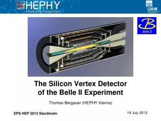
B vertex Si Vertex Detector ( SVD ) 4-layer DSSD Belle Detector K/pseparation • , p0 reconstruction e+-, KLidentification Aerogel Cherenkov Counter n = 1.015~1.030 Electromagnetic Calorimeter CsI(Tl) 16X0 3.5 GeV e+ TOF counter K/pseparation charged particle tracking 8.0 GeV e- Central Drift Chamber momentum, dE/dx 50-layers + He/C2H6 Muon / KLidentification KLm detector 14/15 layer RPC+Fe
The Belle SVD Group SVD Group Frankfurt U., U. Hawaii, Jozef Stefan Inst., Kanagawa U., KEK, Krakow INP, U. Melbourne, National Taiwan U., Niigata U., Nihon Dental U., Nova Gorica U., Osaka U., Princeton U., U. Sydney, Tohoku U., U. Tokyo, Tokyo Inst. Tech., Tokyo Metropolitan U., Toyama NCMT, Vienna IHEP ~100 people
SVD Past and Present SVD1 (1999 ~ 2003 ) SVD2 (Oct 2003 ~ ) 3 layers 23o < q < 139o rmin = 3.0 cm 2 kGy (2M Rad) 4 layers 17o < q < 150o rmin = 2.0 cm 200 kGy (20M Rad) • Unresolved issues • Rad. Hardness • Small acceptance
SVD1 SVD2 : Larger Acceptance Coverage 84 91 % B0J/yKS 14.4 15.8 events/fb-1 +10 % Higher Efficiency Achieved !
SVD1 SVD2 : Smaller Radius ~30% improvement for z-Vertex Resolution
Layer 1 Layer 2 Layer 3 Layer 4 SVD1 SVD2 : Radiation Tolerance Belle IR dose 0.2kGy/year SVD1 Readout VA1 (0.8mm) Rad. Tole. 2kGy SVD2 Readout VA1TA (0.35mm) Rad. Tole. 200kGy Layer 3 Layer 2 Relative Gain Layer 2 (1.2mm) Layer 1 No longer afraid of Radiation Damage No replacement for SVD2 (>3 years) Gain of operation time is priceless
SVD Past and Present SVD1 (1999 ~ 2003 ) SVD2 (Oct 2003 ~ ) Higher efficiency Better resolution Stable operation efficiency 3 layers 23o < q < 139o rmin = 3.0 cm 2 kGy (2M Rad) 4 layers 17o < q < 150o rmin = 2.0 cm 200 kGy (20M Rad) • Unresolved issues • z trigger terminated • Beam BG (non-phys) event suppression • Performance in higher Beam BG • Unresolved issues • Rad. Hardness • Small acceptance
Future prospects of Beam-BG Higher Luminosity is provided by Higher Beam current Higher Luminosity will be provided Peak Luminosity (/nb/sec) by the Higher beam currents Beam currents (A) Beam BG a I2 Beam BG may increase x(2~3) in 2008 2002 2000 2004 2006
SVD Past and Present SVD1 (1999 ~ 2003 ) SVD2 (Oct 2003 ~ ) Higher efficiency Better resolution Stable operation efficiency 3 layers 23o < q < 139o rmin = 3.0 cm 2 kGy (2M Rad) 4 layers 17o < q < 150o rmin = 2.0 cm 200 kGy (20M Rad) • Unresolved issues • z trigger terminated • Beam BG (non-phys) event suppression • Performance in higher Beam BG • Unresolved issues • Rad. Hardness • Small acceptance
Layer1 Layer2 Hit-finding Efficiency Layer3 Layer4 Occupancy Degradation of Hit-finding Efficiency Current BG level Future BG level ? Is there hit or not? • High occupancy • Fake hits • Cluster shape distortion
Degradation of Resolution BG overlay MC B0J/yKS Intrinsic Resolution Intrinsic resolution (mm) residual (mm) BGx3 residual (mm) Occupancy (%)
SVD Past, Present and Future SVD1 (1999 ~ 2003 ) SVD2 (Oct 2003 ~ ) SVD3 from ’07 3 layers 23o < q < 139o rmin = 3.0 cm 2 kGy (2M Rad) 4 layers 17o < q < 150o rmin = 2.0 cm 200 kGy (20M Rad) Software Efforts in progress Almost saturated • Unresolved issues • z trigger terminated • Beam BG (non-phys) event suppression • Performance in higher Beam BG • Unresolved issues • Rad. Hardness • Small acceptance
APV25 x4chip Threshold Occupancy Reduction in SVD3 shaping time of readout chip Occupancy • Performance degradation is not • serious for outer layers • Quick upgrade is necessary (~2007) • Replace only for Layer 1 & 2 • Layer 3 & 4 are same as SVD2 VA1TA Tp~800ns VA1TA x4chip Threshold ~2000ns APV25 Tp~50ns Shorter shaping time gives less occupancy Occupancy ~ 1/13 ~160ns
APV25 Developed for CMS Si Tracker Preamp + CRRC Shaper Multiplexing FADC Sensor waveform sampling Time window ~20ns Further BG reduction Pipeline memory
1500 APV25 (Tp=50ns) 1000 Noise (enc) VA1TA (Tp=800ns) 500 10 20 30 Detector Capacitance (pF) DSSD should be optimized for APV25 Capacitive noise will be serious because of short Tp 800ns 50ns (C : detector capacitance) Capacitance of SVD2 DSSD(r-f) Reduction of Capacitance is Essential
DSSD optimization for APV25 Floating Strips for r-f side (flip pn strip) Reduction of strip width Test sensors by HPK: DSSD x20 (2006), SSD(n-strip) (2005)
Beam Test (4GeV/c p+) withAPV25 + VA1TA system APV25+SSD(n-side) Dec, 2005 SVD2 spare ladders x3
SVD2 ladder Simultaneous operation succeeded for APV25 system with SVD2 system SVD2 ladder APV25 ladder SVD2 ladder
S/N of SSDtowards SVD3 Beam test results 28.4mm ( DSSD 26.1mm) Readout strip S/N=34 Floating strip Charge Collection Eff. = 81%
Laser Scan test for SVD3 DSSD Sep, 2006 Laser 980nm r-f (p strip) z (n strip) Double sided assembly Poor bonding due to Kapton flex in R&D
DSSD for SVD3 Laser scanresults (n-strip) Sep, 2006 SSD Charge Collection Eff. = 85%
Laser Scan results (p-strip) Sep, 2006 Due to poor bonding
Test in High BG area Plan to start from Oct, 2006 Operation with SVD2 spare ladder Check performances Occupancy reduction, etc.
SVD3 mockup test Sufficient clearance is confirmed for the larger Hybrid
Schedule 2006 2007 Oct Nov Dec Jan Feb Mar Apr May Jun Jul Aug Sep full production DSSD SYSTEM TEST INSTALLATION Production / test Design Finalized soon Hybrid Jig prod. / test Layer 1 Layer 2 mount Assembly prod. / test Test w/ ladders Repeater Prod. / test FADC Prod. / test DAQ
Summary • The Belle SVD operated smoothly for the past year • Degradation of performance due to high BG • Hit finding Efficiency (layer 1 & 2), Vertex Resolution • Might be serious ~2008 • Upgrade plan (SVD3) to replace readout chip • VA1TA APV25 (occupancy < 1/10) • Replace only in Layer 1 and 2 (Layer 3 & 4 will be kept) • DSSD is optimized for APV25 • Short strip width to reduce capacitance noise • Test sensors (DSSD & SSD) • Beam test for SSD S/N~34 • Simultaneous operation of APV25 system with SVD2 system • Laser test full production was ordered from HPK • We would like to upgrade SVD3 next year
3.0 SVD3 mechanical issues 4.0 APV25 connector 31.0 65.3 Modifications are necessary because APV25 chip is wider than VA1TA
B0 tag _ B0 _ B0 tag Requirements from Physics High Efficiency ( ~90% ) Good Resolution ( Dz ~ 100mm ) m+ J/y m- (4S) resonance electron (8GeV) KS/L B0 positron (3.5GeV) nm p- bg = 0.425 K+ p- Dz ~ 200mm m+ Asym. = -xCPsin2f1sinDmDt