Download
1 / 47
470 likes | 537 Views
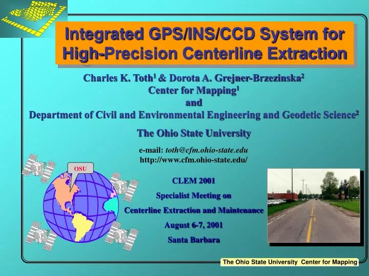
Integrated GPS/INS/CCD System for High-Precision Centerline Extraction. Charles K. Toth 1 & Dorota A. Grejner-Brzezinska 2 Center for Mapping 1 and Department of Civil and Environmental Engineering and Geodetic Science 2 The Ohio State University e-mail: toth@cfm.ohio-state.edu

E N D
Integrated GPS/INS/CCD System for High-Precision Centerline Extraction Charles K. Toth1 & Dorota A. Grejner-Brzezinska2 Center for Mapping1 and Department of Civil and Environmental Engineering and Geodetic Science2 The Ohio State University e-mail: toth@cfm.ohio-state.edu http://www.cfm.ohio-state.edu/ CLEM 2001 Specialist Meeting on Centerline Extraction and Maintenance August 6-7, 2001 Santa Barbara OSU
NCRST - F • Develop, demonstrate, and disseminate cost-effective remote sensing techniques for application to transportation flows National Consortium for Remote Sensing in Transportation - Flows
NCRST - F Application Areas • Traffic Monitoring • Traffic Management • Freight and Intermodal Analysis From Satellite or Airborne Platforms
Progress to Date • Multi-sensor and multi-platform fusion for flow acquisition and interpretation • Findings to date • Positioning quality at flight altitude: 2-5cm per coordinate • Positioning quality on the ground: 20-30cm from 300m altitude • Strong dependence on system calibration
Presentation Outline • Problem description – background • Solution/System design • Hardware configuration • Prototype imaging software suite • Performance experiences • Imaging component • (GPS/IMU positioning system) • Summary
Precision Centerline Mapping cable location
Problem Description • Mapping road lane markers at decimeter-level accuracy while maintaining traffic flow and ensuring safety of survey personnel • Finding the connection between the high-accuracy vehicle navigation and the road surface • Mechanical solutions (early system concept) • Accident hazard • Strong dependence on driver • Non-contact measurements
Proposed Solution • Multisensor data fusion • High speed image acquisition • 2D/3D image processing (photogrammetry) • Computer vision • Real-time processing • Tightly-coupled GPS/INS system • Post-processing • Real-time relative motion support for the real-time image processing system
Y GPS Antenna Digital Camera ZINS -YINS H INS Mapping Concept
Image Post-processing Block Base GPS Station L1 and L2 phase observable Optimal Position, Velocity, Attitude Estimates Strapdown Navigation Solution Tightly Coupled GPS/INS Kalman Filter User Interface, Control & Display Unit Delta V Delta q LN-100 Control Signal Rover GPS Station L1 and L2 EO Data Image Acquisition Control and Storage Time Tag/Sync Host/Slave Communication Real-time Image Processing Block Image Data Pulnix TMC 6700 Digital Color Camera Exposure Control System Design Concept
Imaging Component • Digital frame camera used in tests presented here • based on Lockheed Martin Failrchild 4K 4K CCD sensor • 60mm by 60mm imaging area (15-micron pixel size) • Hasselblad 553 ELX camera body with 50 mm Zeiss lens • 6 second image acquisition rate (0.16 Hz) • Target sensor • Pulnix color digital camera (TMC 6700) • 9 mm by 6 mm imaging area • 30 images per second max acquisition rate (30 Hz)
Image n-1 Image n Relative Motion Estimates Data Acquisition RGB to S Transformation RGB to S Transformation Image Preprocessing Median Filter Binary Conversion Median Filter Binary Conversion Boundary Points Centerline Extraction Boundary Points Centerline Extraction Feature Point Extraction Feature Point Extraction Feature Point Matching Stereo Image Processing Affine Model Formation Centerline Strip Formation Centerline Position Refinement Final Navigation Data Post-processing Export to GIS/CAD Image Processing Concept
Color Separation RGB to IHS transformation
noise Scanline SL Centerline RL P CL Intersection Centerline Extraction (1)
Centerline Extraction (2) Monoscopic solution moderate accuracy High accuracy solution 3D processing
Feature Point Extraction Corner detector: R(x, y) = det[C] – k trace2[C]
s1 m11 m2 s2 m21 m13 s3 m23 Feature Point Matching
Strip Formed Pairwise affine transformation (6-parameter model)
Status • Prototype system implemented in C++ • Experiences • Two sets of images (~15-20) with various road/centerline conditions • Computation-intensive algorithms with convincing performance (post-processing) • Remaining tasks • Real-time data acquisition (camera interface and navigation data from GPS/IMU system) • Software reengineering (multithreading) • Performance tuning (dual P-IV @ 1.7 GHz)
System Calibration Components GPS Lever Arm Calibration CCD INS INS OTF Calibration Camera Calibration Sensor Mount Boresight Misalignment GPS Base
Digital camera GPS antenna LN 100 Test Hardware Configuration
Performance Analysis Tests • Single side-looking camera, tilted downwards by 5°, 4K by 4K B/W imagery • 50-mm focal length • Imagery collected along the surveyed road (edge/center line location) • Stereo-pairs formed by subsequent images • 7-8 m object distance for boresighting • 8-20 m object distance for ground control points (check points)
40.003 40.002 40.001 latitude [deg] 40 Start/end 39.999 39.998 39.997 -83.052 -83.05 -83.048 -83.046 -83.044 -83.042 -83.04 longitude [deg] Start Vehicle Trajectory Centerline test range Calibrationrange
0.45 0.4 0.35 0.3 0.25 RMS [m] 0.2 0.15 0.1 0.05 0 4.165 4.17 4.175 4.18 4.185 4.19 4.195 4.2 4.205 GPS time [sec] 5 x 10 Positioning Accuracy
35 30 25 20 RMS [arcsec] 15 10 5 0 4.165 4.17 4.175 4.18 4.185 4.19 4.195 4.2 4.205 GPS time [sec] 5 x 10 Attitude Accuracy
Boresight Misalignment Performance • Boresight performed by comparison of GPS/INS results with AT solution • Accuracy of the boresight components • 1-2 cm for offsets • 17-22 arcsec for attitude
Testing Positioning Performance Ground coordinate difference for check points measured from different stereo-pairs Ground coordinate difference for check points measured on stereo-pairs from different passes
Positional Error Growth during GPS Outage
Summary • Multisensor all-digital mapping system • Real-time image processing needed • Automatic extraction of centerlines is a reality • Real-time implementation is feasible • Direct orientation can be achieved with high accuracy • Strong GPS-dependency in urban areas • INS support needed (attitude less critical) • Proper system calibration is crucial
Baltimore, MD LIDAR/Digital Image Data Courtesy of The EarthData Group
Panchromatic Image and LIDAR Elevations Plotted as Intensity
+ + + + + + + + + + + + + + + + + + + + + + + + + + + + + + +
Image 1 pixel tessellation Image 2 pixel tessellation LIDAR footprint Image/LIDAR Sampling Pattern 0.4-0.8 1.064
What Could Be the Problem? • Sensor modeling of the camera (interior orientation) • LIDAR sensor modeling (scan angle error) • Digital camera boresight misalignment • LIDAR boresight misalignment • Varying navigation performance • Mechanical flex of the sensor mount • Etc.