Download
1 / 38
380 likes | 405 Views
Explore the role of EXAFS in studying materials properties at small length scales and how synchrotron radiation tools can address these needs. Focus on phase ID, atomic fraction measurements, bond lengths, coordination, and cation site distribution. Discuss the challenges of studying very thin films, beam stability, and sample size. Learn about metallization, crystallization of thin films, and cation distribution in oxides.

E N D
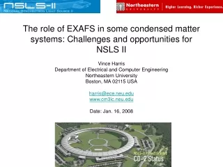
The role of EXAFS in some condensed matter systems: Challenges and opportunities for NSLS II Vince Harris Department of Electrical and Computer Engineering Northeastern University Boston, MA 02115 USA harris@ece.neu.edu www.cm3ic.neu.edu Date: Jan. 16, 2008
Many contributions from: • Aria Yang • Scott Calvin • Bruce Ravel • Joe Woicik • Trevor Tyson • Dave Pappas • Many studies have benefited from the beamline expertise of John Kirkland and Barry Karlin • Maybe as many as 50-75 coauthors to acknowledgde!
Nanoelectronics • Similar Moore’s trend is seen in the minimum feature size. • Gate oxide barriers are below 10nm. 1 nm in some cases. • How does one study materials properties at these length scales? • How does synchrotron radiation tools help address these needs? • Phase ID • Atomic fraction measurements • Bond lengths • Coordination • Phase stability • Cation site distribution and valency • Other Moore technologies • Minimum feature size of ICs • Magnetic storage media • Digital photography pixel density • CPU speed…
Scope • The study of thin films • NSLS I • Focused light beamlines versus nonfocus beamlines • Metallization of diamond (Spintronics) • Crystallization of thin films (phase change) • Strained semiconductors (Nanoelectronics) • Buried layers (Nanoelectronics) • Cation distribution in oxides (Microwave electronics) • Issues • Sample size • Concentration • Thickness • Beam stability • Dynamics
PRB Brief Report 52(11) 7890 (1995) Experimental details MBE grown Fe (0.8nm) EXAFS measurements on X23B NSLS Sample size is 2 mm x 3 mm TEY, room temp, std. conditions Spot size ~250 mm x 250 mm FEFF modeling (FEFF3?) Goal Determine nature of metallization Structure identification Structure stability: bcc vs fcc Bond distances, coordination
PRB Brief Report 52(11) 7890 (1995) Experimental details MBE grown Fe (0.8nm) EXAFS measurements on X23B NSLS Sample size is 2 mm x 3 mm TEY, room temp, std. conditions Spot size ~250 mm x 250 mm FEFF modeling (FEFF3?) Goal Determine nature of metallization Structure identification Structure stability: bcc vs fcc Bond distances, coordination
Challenges Very thin films (6-8 Å, 4-5 ml) Small and very valuable substrates Synthetic diamond 2 mm x 3 mm substrates Beam spot size: 250 mm x 250 mm If beam walks, this is a nightmare! What would be great? In situ measurements during growth In-plane vs out-of-plane measurements What is needed? Higher counts Smaller spots Beam stability Linearity in detector circuitry, challenging. Results FEFF modeling (FEFF 3.11 single scattering) determines Fe-Fe and Fe-C bonds 2-11 Å-1 (k2) Fe-Fe: 2.51 +/- 0.02 Å (~1% in-plane contraction of lattice) Fe-C: 1.84 +/- 0.02 Å (~2.7 atoms) (Fe-C 1.98Å (Fe2C); 2.14Å (Fe3C)) Growth of single crystal austenite PRB Brief Report 52(11) 7890 (1995)
Phys. Rev. B43, 3, 15 Jan. 1991 (Brief Report) • Goals • Nature of strain in GeSi epitaxial films • Experimental • Samples are 34 nm GeSi (31% Ge) • CVD grown films • In-plane vs out-of-plane bond distances • and lattice parameters • EXAFS using FY • Sample spinning • X23A2 beam does not walk • Good linearity and reproducibility • Typically JW many scans merged • Results • Raw data with the first neighbor signal superimposed • Bottom image is the fit to the FF c data • Very accurate bond distances • Strain is distributed in 2nd and 3rd neighbors, • not so much in the NN • JW often uses 50-75 mm diameter • wafer substrates with wide beam spot
Appl. Phys. Lett., Vol. 73, No. 9, 31 August 1998 Experimental Fluorescent yield Spinning samples, wobble In-plane and glancing incidence Results Raw data with best fit of NN bonds Goals and Samples Investigate nature of local distortions in buried layers (InP caps) Important semiconductor materials Samples are in some cases 5-6 nm MOCVD processed
Findings In-As and Ga-As bonds are measured to a high accuracy Epitaxial films experience tetragonal distortions except for x=0.53 sample which had a perfect lattice match to the substrate Noteworthy Large substrates Can this be done on small substrates …probably not Appl. Phys. Lett., Vol. 73, No. 9, 31 August 1998
Error bars determined by background removal and counting statistics Appl. Phys. Lett. 68 (15), 8 April 1996 Experimental details Ion beam sputtered Fe80B20 Metglass™ films 15 nm thick Annealed at different temperatures and different times EXAFS measurements on X23B NSLS Sample size is 5 mm x 5 mm TEY, room temp, std. conditions Spot size ~1 mm x 1 mm No FEFF modeling Linear modeling of standards (poor mans PCA) Goal Determine phases present Determine atomic fraction of each Structural stability Onset of crystallization
Results Mass of sampled data: ~1 nanogram DSC and DTA have 10-3-10-4 gram sensitivity Standards’ data are fit linearly with the following adjustable parameters: -atomic fraction of each phase -Debye-Waller coefficient of the amorphous phase Error bars Determined by fitting the mean, +/- standard deviations Systematic variation of atom fractions until c2 doubles (this is larger) Counting statistics (10 scans of each sample) result in mean and standard deviations Findings Onset of crystallizations is 200K below bulk samples Effective technique for the accurate measurement of phases I wish we could have…. In situ measurements would allow for the calculation of activation energies (in situ heating and film growth) The stability of amorphous phases in small volumes are important for understanding the limits of phase change media Appl. Phys. Lett. 68 (15), 8 April 1996
Experimental Melt spun ribbon samples having excellent soft magnetic properties Amorphous as spun Crystallized by annealing at 550oC (opt. T) for various times EXAFS transmission, RT Goals Does the 1% Cu make a difference and how? IEEE TRANSACTIONS ON MAGNETICS. VOL. 29. NO. 6. 1993 After 8 minutes the Fe is fully crystallized as DO3 (bcc FeSi ordered) phase of ~12-15 nm. On the other hand, the Cu atoms never grow beyond clusters that are ~ 1nm. Clusters have an close packed (fcc) symmetry
The role of 3% Nb Appt. Phys. Lett. 64 (8), 21 February 1994 3% Nb 0% Nb Findings The presence of Nb limits the nucleation and growth of the Cu atoms Without Nb, the Cu is fully crystallized after 2 minutes at temperature The Cu atoms and clusters act as nucleation sites for the DO3 FeSi grains How to improve measurements… Small spot, more light, stable beam position In situ heating Sometimes samples are what they are…. EXAFS details Ribbons: 25 mm thick, 2 mm wide, 20 mm long Problems with sample uniformity Mapping the transmitted beam we find regions of uniform thickness that are about 300 mm x 1000 mm Fe data is easy but of little interest Cu data is challenging The beam walks a little due to large moment arm EXAFS analysis is largely examining Fourier transforms
Partial Radial Distribution Function Fourier transformed Fe EXAFS from Fe3O4 standard illustrating pair correlations leading to A- & B-site fingerprinting Goals The goal is to gather information on both the element specific cation distribution and valency This is true for the manganites as well Magnetic and electronic properties Experimental details Samples are ferrite films prepared by SSP or PLD Size is typically 3-5 mm on a side Thickness is typically 100-200 nm EXAFS: FY or TEY IEEE Trans. Magn. 31, 6, Nov. 1995
Results As shown the peaks from 2-4 Å experience systematic changes FEFF 6: Multiple scattering fits without FEFFIT First determination of cation site distribution in ferrites (one step better than ME) Findings allow interpretation of M vs y trends with increasing Zn These results have provided a methodology to correlate SRO properties to fundamental magnetic properties in the ferrites What we really need is… Site specific, element specific, cation distribution and valency… Appl. Phys. Lett. 68 (15), 8 April 1996
PLD Cu-ferrite Aria Yang, et al., Appl. Phys. Lett., 86, 252510 (2005). Other ferrite systems studied by NRL and NEU researchers since 2000 BM NP Zn-ferrite S.A. Oliver, V.G. Harris, H. Hamdeh and J.C. Ho, Appl. Phys. Lett., 76 (19), 2761 (2000). NP Mn-ferrite (polyol) C. N. Chinnasamy, et al.,J. Appl. Phys. 101, 09M509 (2007). NP Co-ferrite (reverse micelle) Sichu Li, et al., IEEE Trans. On Magn., vol. 37, No. 4, 2350-2352 (2001); Sichu Li, et al., J. Appl. Phys., 87 (9), 6223 (2000). NP MnZn-ferrite (reverse micelle) S. Calvin, E.E. Carpenter, B. Ravel, V.G. Harris, S.A. Morrison, Appl. Phys. Lett., 81(20), 3828 (2002). Sc-doped Ba-hexaferrite A. Yang, Z. Chen, C. Vittoria, and V.G. Harris, J. Appl. Phys., accepted, 2008. ATLAD Cu-ferrite Aria Yang, et al., J. Appl. Phys., accepted, 2008. NP Co-ferrite K. Giri, E. M. Kirkpatrick, P. Moongkhamklang, S. A. Majetich, and V.G. Harris, Appl. Phys. Lett. 80, 2341 (2002); PLD Ni-ferrite C.N. Chinnasamy, et al., J. Appl. Phys., 101, 09M517 (2007). PLD Co-ferrite G. Hu, V.G. Harris, and Y. Suzuki, IEEE Trans. On Magn., vol. 37, No. 4, 2347-2349 (2001); G. Hu, T.K. Nath, C.B. Eom and V.G. Harris, Y. Suzuki, Phys. Rev. B (Rapid Comm.), 62(2), R779 (2000). PLD and ATLAD Mn-ferrite Aria Yang, et al., IEEE Trans. on Magnetics, 42 (10), 2870 (2006); Aria Yang, et al., IEEE Trans. On Magn., vol. 40, pp. 2802-2805, 2004; Xu Zuo, et al., Appl. Phys. Lett., 87, 152505 (2005)
Nanoparticle ferrites: Opportunities and Challenges Technologies are varied, from biosensor, cancer remediation therapies, MRI contrast agents, laser printer toner, radar absorbing materials (stealth) FeCl3.6H2O =0.1 M MnCl2.4H2O = 0.05 M Boiling NaOH Washing Synthesis Nano-particles are formed in the general sequence of nucleation,growth; Ostwald ripening; Aggregation/Agglomeration/Sintering/Coalescence (La Mer’s Law) Experimental
Magnetism and Microstructure studies Fig. TEM micrographs of MnFe2O4 nanoparticles synthesized by using [OH-] molars of (a) 4 M, (b) 2 M, (c) 1 M and (d) 0.425 M. • The small particles are spherical like morphology and the larger particles consist of a mixture of both cubic and spherical particles. • The particle size increased while we decreased the molar concentration of NaOH solution • The Néel temperature is found to increase with particle size • The Néel temperature is significantly higher (400 C) than the bulk MnFe2O4 (300 C). • Contradiction to earlier reports that indicated an increase in TN with reducing particle size and attributed to a finite size scaling. C. N. Chinnasamy, et al., J. Appl. Phys., 101, 09M509 (2007)
EXAFS data, fitting model and Fourier transform fitting results • Multiple scattering paths treatments • Element dependence of first coordination shells • Constraints for Nanoparticles r: distance to the coordination shell in question R: radius of the particle (Normalized) Guess Parameters: Calculated: EXAFS Constraints • Stoichiometry Constraint: S. Calvin, et. al., Phys. Scr., T 115, 744 (2005) FIG. Real part of Fourier transform of EXAFS data and best fits of manganese edge, and iron edge, for both 4 nm and 50 nm samples. The data was Fourier transformed with the k range of 2.6-11.5Å-1, and k weight of 3.
Table. Results determined from the EXAFS best fits (Mn1−dFed)tet[MndFe2-d]octO4 Nanoparticle samples have reduced lattice parameters in comparison to the bulk value of 8.5 Ǻ. Contraction -> Increase of super exchange interaction -> Increase of Néel temperature Results Neel temperature reflects the strength of the exchange Neel temperature increases with particle size but inversely with quench rate What is needed in NP research? Insight into nucleation and growth In situ growth
Automated NP chemical processor Objective: Allowing identical samples to be synthesized on demand in synchrotron and the institution, so that the characterization resources of the home institution’s laboratory can be applied immediately to samples synthesized at the beamline. Scott Calvin, Sarah Lawrence College (SCalvin@slc.edu); Everett E. Carpenter, Virginia Commonwealth University Department of Chemistry
Argonaut Surveyor™ Chemical Processor Configuration of system tested at NSLS A robotic arm can transfer samples and reagents under inert atmospheres x-ray hutch B C F G H nine sources of reagents ten 25-mL reaction vessels temperature controllable from -80°C to 150°C D E A Monochromator B Incident x-ray detector C Flow cell D Lytle detector E Argonaut processor F Waste collection G Control computer H Beamline computer Configuration figure adapted from S. Calvin et al., Rev. Sci. Instrum.76, 016103 (2005).
nylon screws bore Kapton window nylon screws O-ring Kapton window bores (offset to ensure new aliquot displaces old) Custom flow cell Flow cell figures adapted from S. Calvin et al., Rev. Sci. Instrum.76, 016103 (2005).
172 129 86 43 R (Å) eff 0 5.0 5.5 6.0 6.5 7.0 7.5 4.0 4.5 3.5 1.5 2.0 2.5 3.0 1.0 172 129 86 Time (min.) 43 0 Time-resolved mode Example of time-resolved EXAFS data at the iron edge collected at X23B using the Surveyor™ and custom flow cell. Figure adapted from S. Calvin et al., Rev. Sci. Instrum.76, 016103 (2005). Details of reaction are given in that reference.
172 129 86 43 R (Å) eff 0 5.0 5.5 6.0 6.5 7.0 7.5 4.0 4.5 3.5 1.5 2.0 2.5 3.0 1.0 172 129 86 Time (min.) 43 0 Oxygen bonding Time-resolved mode Cation filling Too complicated to be of value (for now) Example of time-resolved EXAFS data at the iron edge collected at X23B using the Surveyor™ and custom flow cell. Figure adapted from S. Calvin et al., Rev. Sci. Instrum.76, 016103 (2005). Details of reaction are given in that reference.
172 129 86 43 R (Å) eff 0 5.0 5.5 6.0 6.5 7.0 7.5 4.0 4.5 3.5 1.5 2.0 2.5 3.0 1.0 172 129 86 Time (min.) 43 0 Oxygen bonding Time-resolved mode Too slow! Little information to be learned in the area of nucleation. Yes, we can slow the kinetics down some, but then we are not duplicating laboratory conditions. Cation filling Too complicated to be of value (for now) Example of time-resolved EXAFS data at the iron edge collected at X23B using the Surveyor™ and custom flow cell. Figure adapted from S. Calvin et al., Rev. Sci. Instrum.76, 016103 (2005). Details of reaction are given in that reference.
AT-LAD grown MnFe2O4 films Objective: Allowing identical samples to be synthesized on demand in synchrotron and the institution, so that the characterization resources of the home institution’s laboratory can be applied immediately to samples synthesized at the beamline. Scott Calvin, Sarah Lawrence College (SCalvin@slc.edu); Everett E. Carpenter, Virginia Commonwealth University Department of Chemistry
Properties of AT-LAD grown films X. Zuo et al., J. Appl. Phys. 97, 10G103 (2005)
Inversion parameters • 4pMs decreased as Inversion parameter (percentage of Mn ions at B sites) increased, which is similar with Cu-ferrite system
X-ray absorption spectra U4B, NSLS, BNL • Sample processed above Pox>5 mTorr more oxidized than samples processed less than 2 mTorr. • Mn3+: 4mB • Mn2+: 5mB • Fe3+: 5mB • over oxidized Mn ions at B site could reduce magnetization • Could Mn and Fe have different valence at different sites?
XAFS µ(E) DAFS I(E) DAFS Basics • Diffraction Anomalous Fine Structure A Feature Of Resonant Elastic Scattering Observed Above Absorption Edges in the Energy Dependence of : • Bragg Peaks • DAFS can be used to isolate the fine structure from a subset of resonant atoms based on their long-range order f’(E) + if’’(E)
Experimental Setup • Do an XAFS-like energy scan with the sample and the detector mounted on a diffractometer • Track the Bragg peak using software or feedback • Advantages: Atom specific, site specific • Bragg reflection chosen: • <222> ~ B sites • <422> ~ A sites • <111> ~ combination of A & B sites (for self-consistency check) • EXAFS Fluorescence (for self-consistency check)
Table. Oxidation charge of Mn and Fe at specific site for both ATLAD MnFe2O4 films Mn edge, 50 mT Mn edge, 1mT
Table. First oxygen neighbor bond distance of Mn and Fe at specific site for both ATLAD MnFe2O4 films Figure. The EXAFS FT data and the fit to the theoretical standards of the Mn (422) and (222) K edge of the 1 mTorr sample.
These parameters, and nothing short, are needed as input for first principles and MF theories This is underway J. Smit and H. P. J. Wijn, Ferrites, John Wiley & Sons, Philips Technical Library, 157 (1959)
What are the central issues in NSLS-II EXAFS beamlines • Sensitivity to sub nanometer thickness is absolutely essential • These thin layers might be buried • The available surface area may be 4-6 mm2 • Dynamics are essential • Film growth • NP synthesis • Magnetic fields • Electric fields • Lasers • What else…..?