Download
1 / 22
230 likes | 356 Views
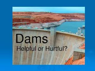
Low-head dams, typically under 15 feet tall, serve to pond water without controlling flow, creating potential hazards. They cause dangerous recirculation, trapping buoyant objects and posing threats to safety. This analysis covers hydraulic principles, flow states, flow measurements, and critical depth calculations essential for evaluating low-head dam operations. Understanding variables like flow velocity, discharge, and hydraulic jumps is crucial for designing safe structures that minimize ecological impact and ensure fish passage while maintaining water quality.

E N D
Engineering Low-Head Dams for Function and Safety Fritz R. Fiedler Department of Civil Engineering University of Idaho
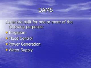
What is a Low-Head Dam? • A dam that is typically less than 15 feet tall • Used to pond water behind them but not control flow • Head: a term that refers to elevation, which can be related to fluid pressure and energy
Why are they dangerous? • Low-head dams cause water to recirculate, thus trapping buoyant objects
y V w Flow in rectangular channels • Side view • Front view Variables: y = flow depth (L) w = channel width (L) A = flow area = yw (L2) V = flow velocity (L/T) Q = discharge = VA (L3/T) q = Q/w (L2/T) Example: y = 2 ft w = 1.5 ft A = 3 ft2 V = 3 ft/s Q = 9 ft3/s q = 6 ft2/s Q
States of flow in open channels • For a given Q, flow in open channels can be subcritical, supercritical, or critical • Subcritical: disturbances on water surface will travel upstream (flow velocity less than wave velocity); high y, low V • Supercritical: disturbances will not travel upstream (flow velocity greater than wave velocity); low y, high V • Critical: flow velocity equals wave velocity
Hydraulic Jump Hydraulic Jump 2 Q = V1A1 = V1y1w 1 Q = V2A2 = V2y2w Image source: http://www.engineering.usu.edu/classes/cee/3500/openchannel.htm Note: Q is constant, so V1y1 = V2y2 (if w constant also)
Froude Number • Ratio of inertia forces to gravity forces • F = V / (gy)0.5 • G = gravitational acceleration • Subcritical flow: F < 1 (gravity forces larger) • Supercritical flow: F > 1 (inertia forces larger) • Critical flow: F = 1
Froude Number Hydraulic Jump 2 1 F1 = V1 / (gy1)0.5 F1 > 1 F2 = V2 / (gy2)0.5 F2 < 1 Image source: http://www.engineering.usu.edu/classes/cee/3500/openchannel.htm
Initial and Sequent Depths • Relationship between depths before (initial) and after (sequent) a hydraulic jump • If y1 and V1 are known, can compute y2
Flow over a dam (weir) As water flows over dam, goes through critical depth, yc at which F = 1 subcritical H yc Hydraulic Jump y0 subcritical P supercritical y1 y2 Q = CwH1.5 or q = CH1.5 where C is a weir coefficient that varies with dam type and H – but we are going to find and measure yc
Critical Flow • At critical flow, F = 1 = Vc / (gyc)0.5 • Vc = (gyc)0.5 • Measure yc at dam, compute Vc then • Q = Vcycw • How is the location of yc found?
Submerged Hydraulic Jump H yc y0 P y1 y2 yt • When yt exceeds y2 the jump becomes submerged • Degree of Submergence = S = (yt – y2) / y2 • When S < 0, jump occurs downstream • When S > 0, jump is submerged • If yt becomes large enough, dam will be submerged too • In the flume, we can control yt
waves travel up waves travel down H yc y0 Dy P y1 y2 yt
Project Steps • Analysis • Measure variables at two discharges • With and without tailwater submergence • Design • Objectives: maintain upstream depth, allow safe passage, create surf wave, minimize cost • Method: simple calculations, physical model studies and testing
Analysis • At low discharge • With no tailwater • Measure: H, P (dam height), yc (must locate), y1, y2, Dy • Compute: Vc, Q, q, F1, C • Evaluate: measurement accuracy, sequent depth equation, floating object passage • With tailwater submerging jump • Measure: yt, Dy, and compute S • Evaluate: measurements, floating object passage • Repeat 1., a., b., … for high discharge
Notes • We can mark, with tape and markers, the water levels right on the flume • Mark the height of the tailwater gate • We will keep flume slope, discharges constant throughout semester • Group Assignment: create a data sheet based on previous slide before next class.
Design • Conceptual • What makes the hydraulic dangerous? • Uniformity, Dy, reverse flow velocity, aeration • How can this knowledge be used to meet objectives? • Analytical / Mathematical • Difficult! • Computer models • Simple equations (e.g., V-notch weir) • Physical models…
Physical Models Image source: http://www.usbr.gov/pmts/hydraulics_lab/about/index.html
Physical Model Testing • Measure variables as in Analysis (and more?) • What has changed? • Compare upstream pool elevations • Aim for little or no difference at both discharges • Test object passage • Surf spot? • Describe the hydraulic • Iterative process! (a.k.a., trial and error)
Practicality and Economics • What types of materials would be required to build your design? (concrete, rip rap, …) • How and when could it be constructed? • If volume of material added is the primary cost, and the cost of this material per unit volume is known – how much would it cost? • Minimum volume = minimum cost: estimate the volume change in your design
Other (Important) Considerations • Water Quality • Sediment and contaminants • Physical • Sediment and stream morphology • Dissolved oxygen • flooding • Ecological • Fish passage • Effects on aquatic life